
Vehicle lamp

A technology for lamps and vehicles, applied in the direction of headlights, road vehicles, vehicle parts, etc., can solve problems such as driver glare, and achieve the effect of suppressing glare

Active Publication Date: 2017-02-22
KOITO MFG CO LTD
View PDF5 Cites 1 Cited by
  • Summary
  • Abstract
  • Description
  • Claims
  • Application Information

AI Technical Summary

Problems solved by technology

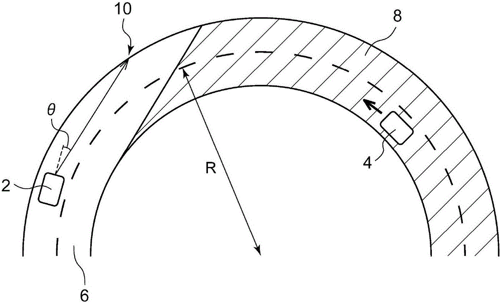
Therefore, the driver of the own vehicle 2 receives glare from the reflected light from the irradiated object 10.

Method used


Image

  • Vehicle lamp
  • Vehicle lamp
  • Vehicle lamp

Examples


Embodiment Construction

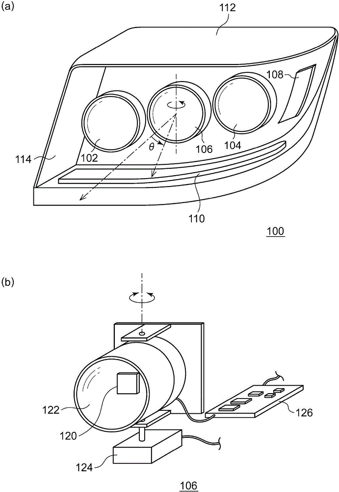
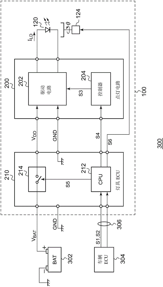
[0059] Below, based on a suitable embodiment, refer to the attached Figure 1 The present invention will be described. The same or equivalent components, members, and processes shown in the drawings are given the same reference numerals, and overlapping descriptions are appropriately omitted. In addition, the embodiment does not limit the invention but is an example, and all the features described in the embodiment or combinations thereof do not limit the essence of the present invention.

[0060] In this specification, the so-called "the state in which part A is connected to part B" includes not only the case where part A and part B are physically directly connected, but also includes the fact that it has no substantial influence on the state of its electrical connection or does not damage the result of their combination. When the function or effect of , part A and part B are indirectly connected through other parts.

[0061] Similarly, the so-called "a state in which part ...


PUM


Abstract

The light source of the present disclosure spot-irradiates a distant place in front of a vehicle. The turn on / off circuit supplies a driving current ILD to the light source 120 to turn on the light source. The swivel mechanism swivels the light source. The turn on / off circuit reduces a light quantity of the light source as a swivel angle theta of the swivel mechanism is large.

Description

technical field [0001] The present invention relates to vehicle lamps used in automobiles and the like. Background technique [0002] Halogen lamps and HIDs (High Intensity Discharge High Intensity Discharge Lamps) have traditionally been the mainstream as light sources for vehicle lamps, especially headlights. However, in recent years, LEDs (Light Emitting Diodes) and laser diodes (also called The development of vehicle lamps using semiconductor light sources such as "semiconductor lasers" has been advanced. [0003] In order to improve the visibility at a distance, vehicle lamps equipped with lights that focus on a longer distance than the normal high beam (called "additional high beam") have been developed. High directivity is required for the light source of the additional high beam, so a laser diode or similar high-brightness semiconductor light source is used. In addition, high-intensity light sources such as laser diodes and LEDs are sometimes used for normal high b...

Claims


Application Information

Patent Timeline
Patent Type & Authority Applications(China)
IPC IPC(8): F21S8/10F21V23/00F21V23/04H05B33/08H05B37/02F21W101/02F21W101/10F21Y115/10F21Y115/30F21W107/10H05B44/00
CPCF21S41/14F21S41/141F21S41/20F21V23/003F21V23/04F21W2102/00F21W2107/10H05B45/10H05B47/10B60Q1/12B60Q1/1407B60Q1/122B60Q2300/054B60Q2300/056B60Q2300/112B60Q2300/122B60Q2300/322B60Q1/0076B60Q1/0094B60Q1/085B60Q1/143B60Q2300/42
Inventor 市川知幸
Owner KOITO MFG CO LTD
Learn More