Optical laminate, polarizer, and display apparatus
a technology of optical laminates and polarizers, applied in the field of optical laminates, can solve the problems of disadvantageous cost-benefit multi-layer arrangement and deterioration of anti-glare properties, and achieve the effects of maintaining anti-glare properties, reducing cost, and reducing the effect of glar
- Summary
- Abstract
- Description
- Claims
- Application Information
AI Technical Summary
Benefits of technology
Problems solved by technology
Method used
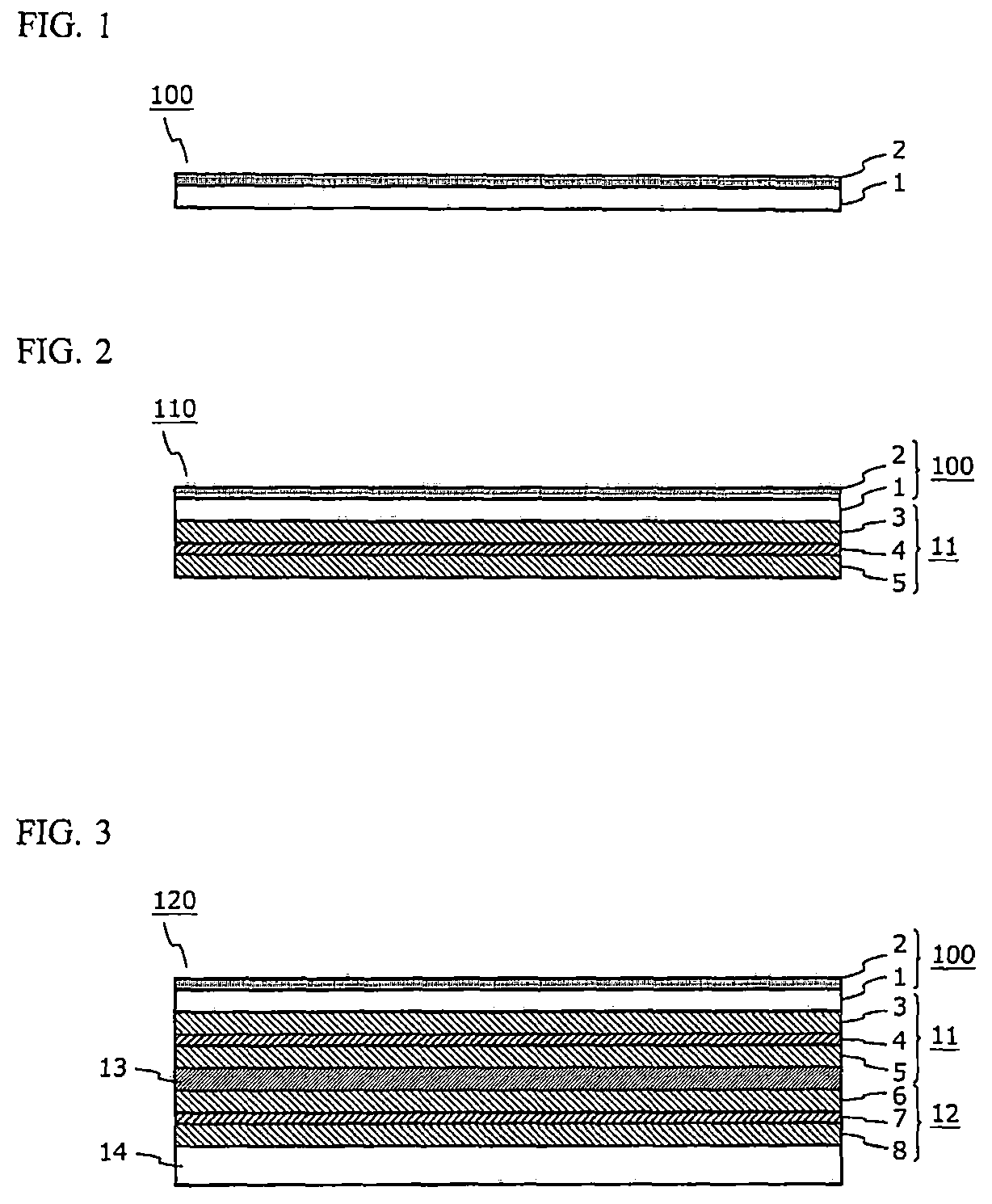
Image

Examples
examples
[0063]Examples in which an optical laminate according to the embodiment is specifically implemented or carried out will now be described.
[0064](Production Method for Optical Laminate)
[0065]As the translucent substrate, a triacetylcellulose film having a thickness of 40 μm was used. A coating liquid for forming an optical functional layer described below was applied to the translucent substrate, followed by drying (vaporizing the solvent). Thereafter, the resultant coating film was caused to undergo polymerization so that the coating film is cured. Thus, the optical functional layer was formed.
[0066][Coating Liquid for Forming Optical Functional Layer][0067]Base resin: UV / EB curable resin Light Acrylate PE-3A (pentaerythritol triacrylate, manufactured by Kyoeisha Chemical, Co., Ltd.), refractive index: 1.52[0068]Resin particles (organic filler): crosslinked styrene narrow-dispersion particles SX350H (manufactured by Soken Chemical & Engineering Co., Ltd.), average particle size: 3.5 ...
PUM
| Property | Measurement | Unit |
|---|---|---|
| height | aaaaa | aaaaa |
| area | aaaaa | aaaaa |
| total light transmittance | aaaaa | aaaaa |
Abstract
Description
Claims
Application Information
 - Generate Ideas
- Intellectual Property
- Life Sciences
- Materials
- Tech Scout
- Unparalleled Data Quality
- Higher Quality Content
- 60% Fewer Hallucinations
Browse by: Latest US Patents, China's latest patents, Technical Efficacy Thesaurus, Application Domain, Technology Topic, Popular Technical Reports.
© 2025 PatSnap. All rights reserved.Legal|Privacy policy|Modern Slavery Act Transparency Statement|Sitemap|About US| Contact US: help@patsnap.com