A Gravity Driven Caliper Disc Brake

A disc brake and gravity-driven technology, applied in the direction of brake type, axial brake, brake actuator, etc., can solve the problems of complex structure of the brake, no longer usable, reduced braking performance, etc., and achieve uniform force , reduce the impact, reduce the impact of the impact

Active Publication Date: 2018-08-10
SHANDONG KEDA ELECTROMECHANICAL TECH CO LTD
View PDF1 Cites 0 Cited by
  • Summary
  • Abstract
  • Description
  • Claims
  • Application Information

AI Technical Summary

Problems solved by technology

The structure of the above-mentioned brake is complex and the production cost is very high, and once the spring of this type of brake is aged, its braking performance will be greatly reduced and it cannot be used any longer. How big is the braking force received, and how much force is required to release the brake?

Method used


Image

  • A Gravity Driven Caliper Disc Brake
  • A Gravity Driven Caliper Disc Brake
  • A Gravity Driven Caliper Disc Brake

Examples


Embodiment Construction

[0026] The present invention will be further described in detail below in conjunction with the accompanying drawings and specific embodiments, but the present invention is not limited to these embodiments.

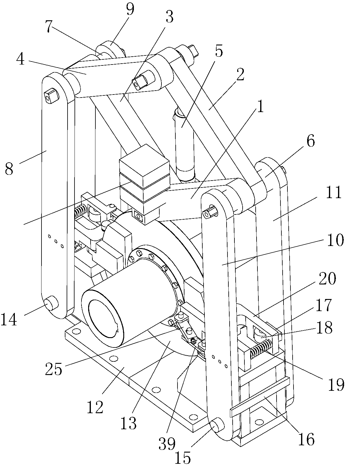
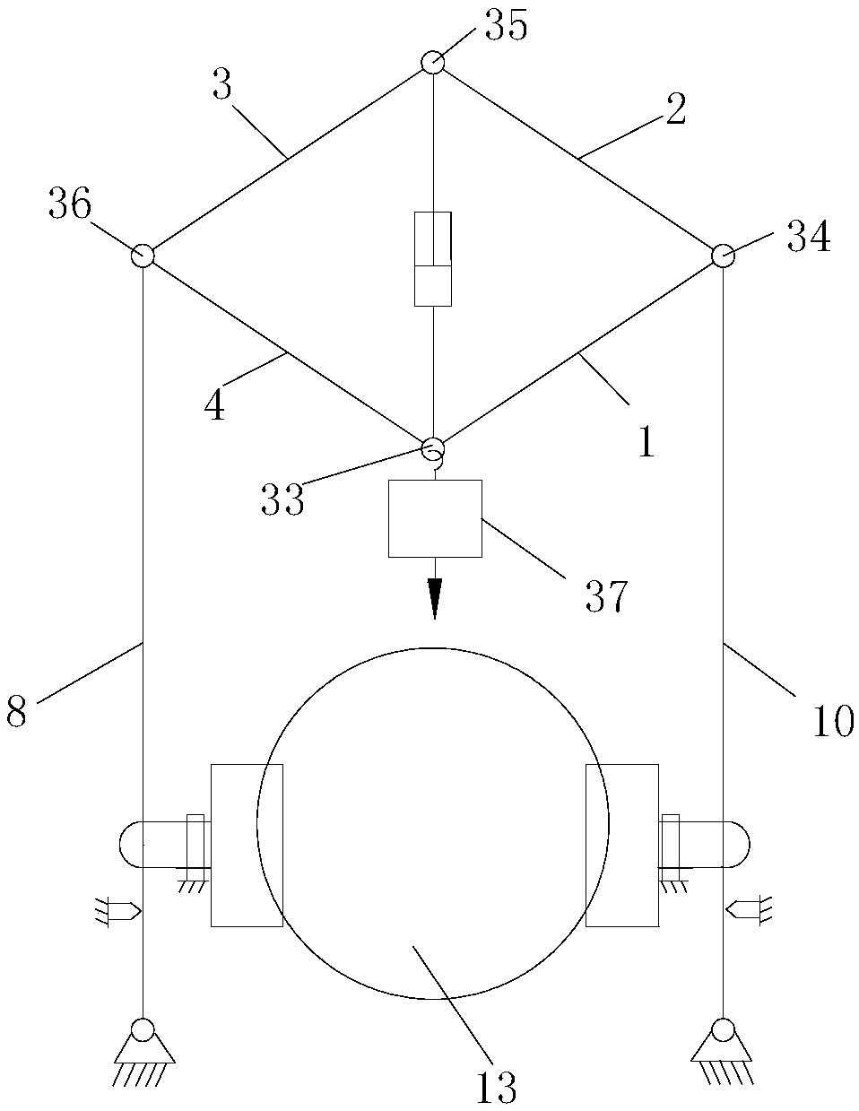
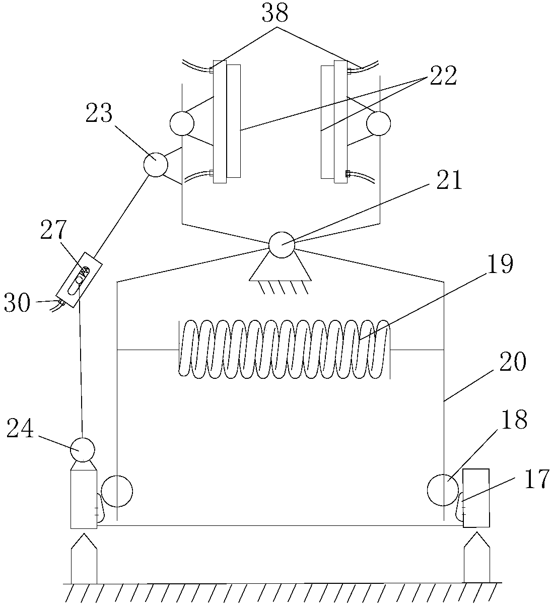
[0027] Such as Figure 1 to Figure 4 As shown, a gravity-driven caliper structure disc brake includes a braking system and a driving system. The braking system includes a caliper brake mechanism for clamping the brake disc 13 and a caliper brake mechanism for touching the brake disc 13. There are four brake arms for the action of the mechanism, and the four brake arms are opposite to each other. They are respectively the right front brake arm 10, the right rear brake arm 11, the left front brake arm 8 and the left rear brake arm. arm 9, the brake system also includes a right transmission shaft 6 and a left transmission shaft 7, the upper part of the right front brake arm 10 and the upper part of the right rear brake arm 11 are sleeved on the right transmission shaft 6, the...


PUM


Abstract

The invention discloses a gravity driven caliper disc brake. The gravity driven caliper disc brake comprises a braking system and a driving system, the braking system comprises a caliper-shaped braking mechanism and braking arms, wherein the caliper-shaped braking mechanism is used for clamping a braking disc and the braking arms are used for making contact with the caliper-shaped braking mechanism and enable the caliper-shaped braking mechanism to act. The driving system comprises a four rod linkage mechanism and a plurality of balancing weights, the four rod linkage mechanism comprises a first connecting rod, a second connecting rod, a third connecting rod and a fourth connecting rod, and the first connecting rod, the second connecting rod, the third connecting rod and the fourth connecting rod are sequentially hinged to one another head to tail. The driving system also comprises a driving mechanism which is connected with the hinged joint of the second connecting rod and the third connecting rod and drives the hinged joint to conduct lifting movement, and the balancing weights can be sequentially stacked on the hinged joint of the first connecting rod and the fourth connecting rod. The gravity driven caliper disc brake adopts a way of gravity braking and is safer, timelier and more accurate than spring braking of an existing electro-hydraulic disc brake.

Description

technical field [0001] The invention relates to a disc brake, in particular to a gravity-driven pincer structure disc brake. Background technique [0002] At present, electrohydraulic disc brakes are the main high-speed braking devices in the industrial field. Electrohydraulic disc brake is a normally closed structure braking device commonly used in coal mines, metallurgy, ports and wharves and other industries. Most electrohydraulic disc brakes are devices that slow and / or stop rotating machinery by applying pressure to a disc with brake pads. [0003] The patent application document with application number 201310740695.2 discloses an electrohydraulic arm disc brake, which includes two parts: a brake frame and a pusher. The brake frame includes a base, a brake shoe assembly, a main arm assembly, and an auxiliary arm. assembly, a lever assembly, and a spring assembly, the brake shoe assembly is composed of brake shoe 1 and brake shoe 2, and the main arm assembly and auxili...

Claims


Application Information

Patent Timeline
Patent Type & Authority Patents(China)
IPC IPC(8): F16D55/224F16D65/14F16D66/02F16D121/04F16D121/14F16D125/68
CPCF16D55/2245F16D65/14F16D66/02F16D2055/002F16D2055/0029F16D2055/0041F16D2066/003F16D2121/04F16D2121/14F16D2125/68
Inventor 包继华姜雪李国清李凤媛房建梅李永浩陈阔海
Owner SHANDONG KEDA ELECTROMECHANICAL TECH CO LTD
Why Eureka
Try Eureka