
Shaft construction method and construction structure

A construction method and shaft technology, which are applied to shaft equipment, earth-moving drilling, reverse drilling, etc., can solve the problems of high construction cost, complex construction process, and high technical requirements, and achieve low construction cost, short auxiliary time, and reduced Effects of complexity

Active Publication Date: 2019-09-17
湖北三宁矿业有限公司
View PDF7 Cites 0 Cited by
  • Summary
  • Abstract
  • Description
  • Claims
  • Application Information

AI Technical Summary

Problems solved by technology

These methods are all conventional construction methods, and all have defects in varying degrees, such as: complex construction process, high technical requirements, high construction cost, etc.

Method used


Image

  • Shaft construction method and construction structure
  • Shaft construction method and construction structure

Examples


Embodiment Construction

[0032] The following will clearly and completely describe the technical solutions in the embodiments of the present invention with reference to the accompanying drawings in the embodiments of the present invention. Obviously, the described embodiments are only part of the embodiments of the present invention, not all of them. Based on the embodiments of the present invention, all other embodiments obtained by persons of ordinary skill in the art without creative efforts fall within the protection scope of the present invention.

[0033] It should be noted that all directional indications (such as up, down, left, right, front, back...) in the embodiments of the present invention are only used to explain the relationship between the components in a certain posture (as shown in the accompanying drawings). Relative positional relationship, movement conditions, etc., if the specific posture changes, the directional indication will also change accordingly.

[0034] In addition, in t...


PUM


Abstract

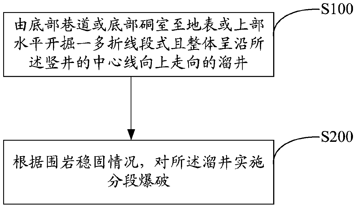
The invention discloses a construction method and structure for a vertical shaft. The vertical shaft construction method comprises the steps of digging a draw shaft horizontally from a bottom roadway or a bottom underground chamber to the earth surface or above, wherein the draw shaft has multiple fold line segments and the whole body of the draw shaft moves upward along the center line of the vertical shaft; according to the stabilization and fixation condition of surrounding rocks, conducting segment blast on the draw shaft. According to the construction method and structure for the vertical shaft, the complexity of the construction process of the vertical shaft can be reduced, the construction of the vertical shaft is more simple and convenient, and the construction cost of the vertical shaft is reduced.

Description

technical field [0001] The invention relates to the technical field of underground mine construction, in particular to a construction method and construction structure of a shaft. Background technique [0002] At present, the main methods for constructing shafts in domestic underground mines include hanging tank method, climbing tank method, deep hole blasting method, and raised shaft method. These methods are conventional construction methods, and all have defects in varying degrees, such as: complex construction process, high technical requirements, high construction cost, etc. Contents of the invention [0003] The present invention aims to solve one of the technical problems in the related art at least to a certain extent. Therefore, the main purpose of the present invention is to provide a construction method for a shaft, which aims at reducing the complexity of the construction process of the shaft, making the construction of the shaft simpler and more convenient, a...

Claims


Application Information

Patent Timeline
Patent Type & Authority Patents(China)
IPC IPC(8): E21D3/00F42D3/00
Inventor 王学梁高本铭赵磊黄腾龙
Owner 湖北三宁矿业有限公司
Learn More