Highly pressurized liquid driven eccentric sheave type bottom hole sleeve cutter

A technology of high-pressure liquid and eccentric wheel, which is applied in the direction of wellbore/well components, earthwork drilling and production, etc., can solve the problems of unfavorable environmental protection and energy saving, complicated and cumbersome structure of casing cutter, and low efficiency of use, so as to save materials , simple structure and high efficiency

Active Publication Date: 2017-02-22
JILIN UNIV
View PDF8 Cites 2 Cited by
  • Summary
  • Abstract
  • Description
  • Claims
  • Application Information

AI Technical Summary

Problems solved by technology

[0003] The purpose of the present invention is to solve the problems that the existing casing cutter has complex and cumbersome structure, low use efficiency, is not conducive to environmental protection and energy saving, and is prone to fatigue damage, and provides a low cost, high use efficiency, and material saving A high-pressure liquid-driven eccentric wheel bottomhole casing cutter that is not prone to fatigue, simple in structure, and easy to operate

Method used


Image

  • Highly pressurized liquid driven eccentric sheave type bottom hole sleeve cutter
  • Highly pressurized liquid driven eccentric sheave type bottom hole sleeve cutter
  • Highly pressurized liquid driven eccentric sheave type bottom hole sleeve cutter

Examples


Embodiment Construction

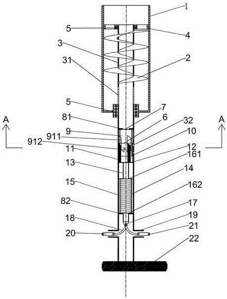
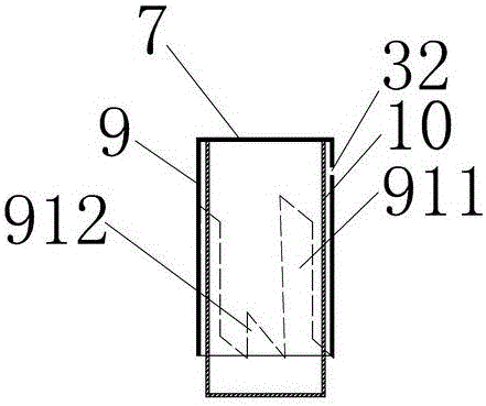
[0034] see figure 1 , figure 2 , image 3 , Figure 4 , Figure 5 and Image 6 As shown, it is an embodiment of the present invention, including an upper cylinder body 1, a helical blade 2, a helical blade installation shaft 3, a helical blade limit seat 4, several balls 5, a lower cylinder sleeve 6, and an automatic rebound mechanism. Base 7, upper limit seat 81, lower limit seat 82, upper cylinder outer sleeve 9, upper cylinder inner sleeve 10, lower cylinder outer sliding column 11, automatic rebound mechanism lower base 12, connecting column 13, spring Centralizing cylinder 14, constant loose spring 15, spring upper base 161, spring lower base 162, pin 17, crank connecting rod 18, cutting tooth slideway 19, cutting tooth base 20, cutting tooth 21 and detachable eccentric wheel 22;

[0035] Wherein the screw blade 2 and the screw blade installation shaft 3 are all arranged in the upper cylinder body 1, the screw blade 2 is fixedly arranged on the screw blade installat...


PUM


Abstract

A highly pressurized liquid driven eccentric sheave type bottom hole sleeve cutter comprising an upper cylinder, spiral blades, a spiral blade mount shaft, a spiral blade limit seat, a plurality of balls, a lower cylinder sleeve, an automatic rebound mechanism upper pedestal, an upper limit seat, a lower limit seat, an upper cylinder outer sleeve, an upper cylinder inner sleeve, a lower cylinder outer slide column, an automatic rebound lower pedestal, a connecting pole, a spring centralizing barrel, a normally loose spring, a spring upper pedestal, a spring lower pedestal, a pin shaft, a crank connecting rod, a cutting tooth slideway, a cutting tooth pedestal, cutting teeth, and a detachable eccentric sheave 22; the highly pressurized liquid driven eccentric sheave type bottom hole sleeve cutter is simple in structure, low in cost, high in usage efficiency, easy to operate, saves materials, and is hard to be fatigued and damaged.

Description

technical field [0001] The invention relates to a casing cutter, in particular to a high-pressure liquid driven eccentric wheel type bottom hole casing cutter. Background technique [0002] At present, the existing casing cutter adopts the drill pipe to transmit the torque, the structure is complex and cumbersome, and more energy will be wasted during use, which is not conducive to environmental protection (such as CN 203796205U;); due to the cumbersome structure, the energy transmission process is complicated, When cutting deep well casing, the drill pipe is prone to serpentine bending and insufficient torque; in addition, the existing casing cutter contains multiple sets of spring wearing parts, and the spring is prone to lose elasticity under fatigue load. It is not conducive to repeated use; in addition, some casing cutters (such as 201020139208.1) have a cumbersome structure and increase useless work during use, resulting in energy waste and low efficiency, and they are...

Claims


Application Information

Patent Timeline
IPC IPC(8): E21B29/00
CPCE21B29/002
Inventor 郭威赵帅李强孙友宏刘世畅韩婧李家晟孙中瑾周科吕世东
Owner JILIN UNIV
Why Eureka
Try Eureka