Rubber damper with presettable initial rigidity

A technology of initial stiffness and damper, which is applied in the direction of building components, earthquake resistance, building types, etc., can solve the problems of increasing the volume of earthquake-resistant structures, poor tensile capacity, inability to stretch, energy consumption and vibration reduction, etc., to reduce volume and reduce The Effect of Seismic Isolation Costs

Inactive Publication Date: 2017-02-22
NANJING DADE DAMPING TECH CO LTD
View PDF6 Cites 1 Cited by
  • Summary
  • Abstract
  • Description
  • Claims
  • Application Information

AI Technical Summary

Problems solved by technology

[0003] The strong bearing capacity of the rubber shock-isolating pad is mainly reflected in the compressive capacity, while the tensile capacity is often poor. Under the action of high tensile load, the rubber shock-isolating pad is easy to be torn, precisely because of the weak tensile capacity. Defects lead to certain restrictions on the application of rubber shock-isolating pads in the field of shock-isolation technology
[0004] The invention patent application with the publication number CN101769015A discloses a "Laminated Rubber Shock Isolation Bearing Tensile Mechanism", which includes an upper connecting seat, a lower connecting seat and a laminated rubber clamped between the upper and lower connecting seats. The shock isolation support, the upper connection seat is provided with an "L" shaped upper reaction force arm, the lower connection seat is provided with an inverted "L" shaped lower reaction force arm, and the "L" shaped upper reaction force arm Between the reaction force arm and the horizontal lateral side of the inverted "L"-shaped lower reaction force arm, there is a laminated rubber shock-isolation support clamped by the two in reverse; when the tensile structure is compressed, The pressure is borne by the shock-isolation support clamped between the upper and lower connecting seats; when the tensile structure is pulled, the tension is supported by the "L"-shaped upper reaction force arm and the inverted "L"-shaped lower reaction force arm. The force arm is converted into the pressure on the seismic isolation bearing clamped between the two directions; although this makes the structure have tensile capacity, it still has the following disadvantages: (1) the isolation bearings are divided by different isolation bearings. Bear bi-directional loads, so at least two laminated rubber seismic isolation bearings are required, which not only costs more, but also increases the volume of the seismic structure; (2) When a seismic isolation bearing is compressed, there must be a seismic isolation bearing The bearing is under tension, and the seismic isolation bearing under tension also has the risk of tearing; (3) It is difficult to ensure that the characteristics of the two isolation bearings are the same in technology, so the isolation effect is different in different directions of force
Since the deformation element of the rubber shock absorber is rubber, the above three means of changing the effective working length of the spring are obviously not suitable for the rubber shock absorber; Can only compress energy dissipation and vibration reduction, not stretch energy dissipation and vibration reduction

Method used


Image

  • Rubber damper with presettable initial rigidity
  • Rubber damper with presettable initial rigidity
  • Rubber damper with presettable initial rigidity

Examples


example 1

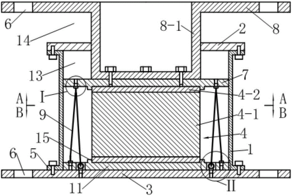
[0040] see Figure 1-5 , the damper described in this example is a vertical shock-isolation device (also known as a vertical shock-isolation support) for building anti-seismic, which includes a guide sleeve 1, a first end cover 2, a second end cover 3 , Rubber shock-isolating pad 4 and back pressure device.

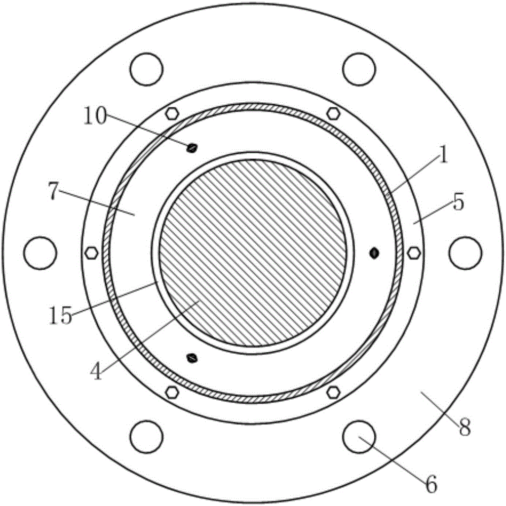
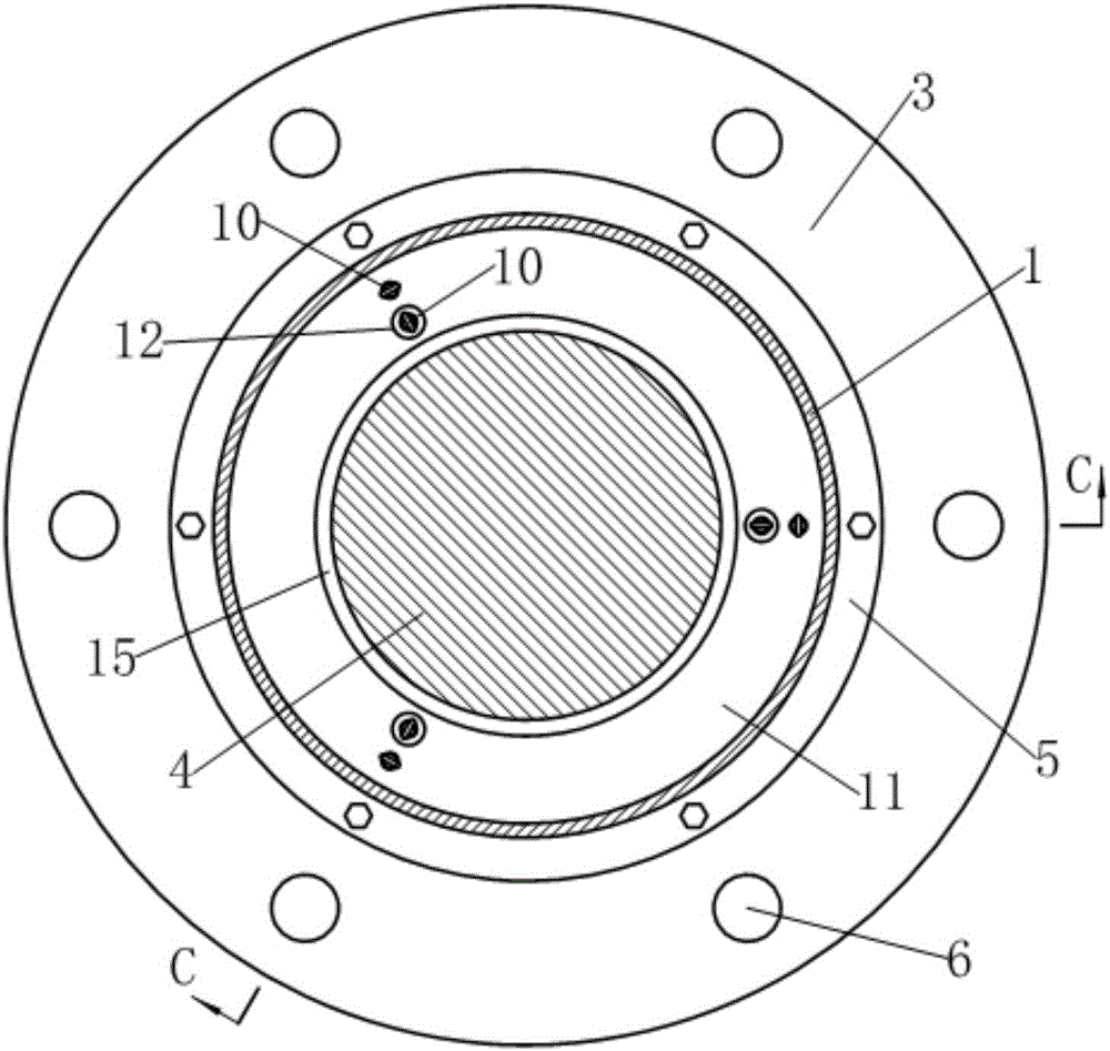
[0041] see Figure 1~3 , the guide sleeve 1 is in the shape of a circular tube, and its two ends extend radially outward to form a flange 5 . The first end cover 2 is connected to the flange 5 on the upper end of the guide sleeve 1, and the center is provided with a guide hole; the second end cover 3 is disc-shaped, and the surrounding edges are provided with mounting holes 6. The guide sleeve 1 is fixed on the middle part of its upper surface by the flange plate 5 provided at the lower end.

[0042] see Figure 1~3 , the driving member is composed of a dynamic pressure plate 7 and an upper connecting plate 8, wherein the edge of the upper connecting plate 8 is provid...

example 2

[0055] see Figure 6-11 , the damper described in this example is also a vertical shock-isolation device for building anti-seismic, and on the basis of example 1, the following improvements are mainly made: (1) the pre-compressed steel wire rope 9 is increased by three to four; (2) replace the eye screw 10 as the wire rope changing element with a U-shaped member 17; (3) replace the eye screw 10 at the other end of the fixed preloaded wire rope 9 with a wire rope self-locking anchor 16; (4 ) thicken the middle part of the second end cover 3 and bulge upwards to form an inverted washbasin shape, so as to install the wire rope self-locking anchor 16; (5) correspondingly change the described back pressure device to:

[0056] The anti-pressure device consists of four pre-compressed steel wire ropes 9, four U-shaped members 17 as wire rope direction-changing elements, a floating counter-pressure steel plate 11, four eyebolts 10 for fixing one end of the pre-compressed steel wire rop...

example 3

[0066] see Figures 12 to 14 , this example is a damper used for seismic reinforcement of building structures, the damper includes a guide sleeve 1, the two ends of the guide sleeve 1 are respectively fixed with a first end cover 2 and a second end cover 3, and a rubber septum is arranged inside Vibration pad 4, a driving member extends from the center of the first end cover 2 at one end of the guide sleeve into the guide sleeve 1 and presses on the rubber shock-isolating pad 4; The first driving rod 18 connected into one body is formed, the end of the first driving rod 18 is provided with a connecting ring 18-1 threadedly butted together with it, and the connecting ring 18-1 is provided with a hinged hole 19, so Described movable platen 7 is dynamically matched with guide sleeve 1. The outer diameter of the rubber vibration-isolating pad 4 is smaller than the inner diameter of the guide sleeve 1, and an annular space is formed between the two.

[0067] see Figure 12 , the...


PUM


Abstract

The invention relates to a rubber damper with the presettable initial rigidity. The rubber damper is characterized in that a back pressure device is further arranged inside a guiding sleeve, the back pressure device comprises three or more prepressing steel wire ropes, steel wire rope turning components with the same number as the prepressing steel wire ropes and a floating back pressure steel plate, wherein the prepressing steel wire ropes are distributed inside an annular space between the guiding sleeve and a rubber shock insulation cushion in a folding line mode, one end of each prepressing steel wire rope is symmetrically fixed to the floating back pressure steel plate around the axis of the guiding sleeve, the other end of each prepressing steel wire rope is returned after penetrating through the corresponding steel wire rope turning component in a winding mode and then penetrates through the floating back pressing steel plate from a fixing point, on the floating back pressure steel plate, of the prepressing steel wire rope to be fixed to a second end cover; the prepressing steel wire rope is tensioned to tension needed by the preset initial rigidity, and the rubber shock insulation cushion is clamped between the floating back pressure steel plate and a driving component all the time.

Description

technical field [0001] The invention relates to a building anti-vibration (or vibration) device, in particular to a damping device containing a rubber shock-isolating pad. Background technique [0002] Rubber shock-isolating pad is a kind of shock-isolating device with rubber as the deformation element. Due to the advantages of low cost, strong bearing capacity and low natural vibration frequency, rubber shock-isolating pad is widely used in heavy-duty occasions such as buildings and bridges. [0003] The strong bearing capacity of the rubber shock-isolating pad is mainly reflected in the compressive capacity, while the tensile capacity is often poor. Under the action of high tensile load, the rubber shock-isolating pad is easy to be torn, precisely because of the weak tensile capacity. Defects lead to certain restrictions on the application of rubber shock-absorbing pads in the field of shock-isolation technology. [0004] The invention patent application with the publicat...

Claims


Application Information

Patent Timeline
Patent Type & Authority Applications(China)
IPC IPC(8): E04B1/98E04H9/02
CPCE04H9/021
Inventor 谢韩涛刘汶津韩磊张少华
Owner NANJING DADE DAMPING TECH CO LTD
Why Eureka
Try Eureka