A mold changing device for the lower mold of the folding mechanism of the bag sticking machine

The technology of a bag sticking machine and a rotating mechanism is applied in the direction of cloth feeding mechanism, sewing machine components, textiles and paper making, etc. It can solve the problems that the lower mold cannot be pulled out from the pocket, high labor cost, and low efficiency, etc., and achieves simple structure and low cost. The effect of labor intensity and ease of retraction

Active Publication Date: 2022-02-01
SHANGHAI WEISHI MACHINERY
View PDF8 Cites 0 Cited by
  • Summary
  • Abstract
  • Description
  • Claims
  • Application Information

AI Technical Summary

Problems solved by technology

[0003] During the working process of the bag sticking machine, the electromagnet first attracts the lower template, and the lower mold of the folding mechanism is inserted into the bottom of both sides of the pocket cloth to complete the folding action of the pocket cloth, and then when the folding mechanism is reset, the lower mold It needs to be pulled out from the bottom of the pocket cloth. When the bottom of the pocket is wide and the top is narrow, the upper opening is small. After the lower mold is inserted and the folding action is completed, the lower mold cannot be pulled out. Therefore, the existing technology is suitable for pockets with a wide bottom and a narrow top Patch pockets are generally sewn by hand, resulting in reduced efficiency and high labor costs
[0004] For example, the Chinese patent document whose publication number is CN104908358A discloses a bag-folding auxiliary top-up mechanism for a bag-sticking machine. When the bag is folded, the bottom of the bag is wide and the top is narrow, so the lower die cannot be pulled out from the pocket.

Method used


Image

  • A mold changing device for the lower mold of the folding mechanism of the bag sticking machine
  • A mold changing device for the lower mold of the folding mechanism of the bag sticking machine
  • A mold changing device for the lower mold of the folding mechanism of the bag sticking machine

Examples


Embodiment Construction

[0026] The present invention will be further described below in conjunction with the accompanying drawings and specific embodiments.

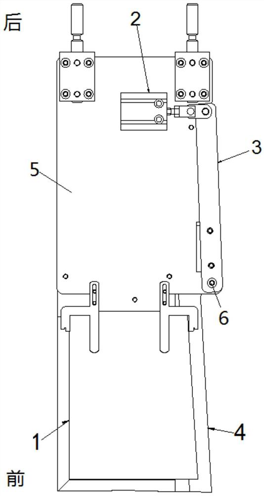
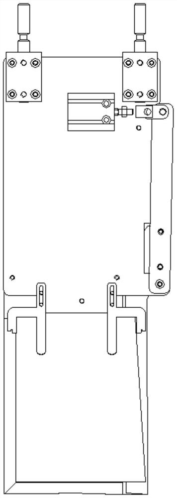
[0027] see Figure 1-2 , a mold changing device for the lower mold of the hemming mechanism of the bag sticking machine, the lower mold of the hemming mechanism includes a connecting plate 5, and the front part of the connecting plate is fixedly connected to the lower mold 1 for inserting into the pocket cloth below, and the connecting plate 5 At least one side is provided with a swing arm 3, and the swing arm 3 is fixedly connected to the die-changing sheet 4, and the connection part has a fixed rotating mechanism 6, and the swing arm 3 is fixedly connected to the push rod of the power source 2, and the power source During action, the swing arm 3 drives the mold changing piece 4 to swing around the rotating mechanism 6. When folding the bag, the front part of the mold changing piece 4 opens outwards, and when the mold is demoulded, the front p...


PUM


Abstract

The invention relates to a die-changing device for the lower mold of the hemming mechanism of the bag sticking machine. The lower mold of the hemming mechanism includes a connecting plate, and the front part of the connecting plate is fixedly connected to the lower mold for inserting into the bottom of the pocket cloth. At least one side of the connecting plate is provided with a There is a swing arm, the swing arm is fixedly connected with the variable die, and the connecting part has a fixed rotating mechanism, the swing arm is fixedly connected with the push rod of the power source, when the power source is in motion, the swing arm drives the variable die to swing around the rotating mechanism , when the bag is folded, the front part of the variable mold piece is opened outwards, and when the mold is demoulded, the front part of the variable mold piece is retracted inward, so that the lower mold can come out from under the pocket cloth. The invention provides a mold changing device for the lower mold of the hemming mechanism of the bag sticking machine, which can change the shape of the lower mold of the hemming mechanism. It comes out from the bottom of the pocket cloth; using the principle of leverage, powered by the power source, the swing arm and the mold changing piece rotate around the axis to realize the mold changing function. The structure is simple, the power source can be retracted freely, and there is no dead point.

Description

technical field [0001] The invention relates to a bag pasting machine, in particular to a mold changing device for a lower mold of a folding mechanism of a bag pasting machine, which belongs to the technical field of industrial sewing machines. Background technique [0002] Pocket patching machine is mainly used in the sewing of jeans and shirt pockets. Flat stitch sewing and tacking can be completed at one time. It is suitable for sewing various jeans back pockets, shirt pockets, and other irregularly shaped parts in garment processing. suture. [0003] During the working process of the bag sticking machine, the electromagnet first attracts the lower template, and the lower mold of the folding mechanism is inserted into the bottom of both sides of the pocket cloth to complete the folding action of the pocket cloth, and then when the folding mechanism is reset, the lower mold It needs to be pulled out from the bottom of the pocket cloth. When the bottom of the pocket is wid...

Claims


Application Information

Patent Timeline
Patent Type & Authority Patents(China)
IPC IPC(8): D05B35/06D05B21/00
CPCD05B21/00D05B35/062
Inventor 姚型楷李振宝
Owner SHANGHAI WEISHI MACHINERY
Why Eureka
Try Eureka