A mobile automatic sand loading machine rotary mechanism

A slewing mechanism, mobile technology, applied in the direction of conveyors, conveyor objects, transportation and packaging, etc., can solve the problems of increasing the wall thickness of the slewing mechanism, small belt extension distance, small rotation angle, etc., to increase the key extension Effect of increasing distance, increasing service life, and increasing extension length

Inactive Publication Date: 2018-09-25
山东大军机械有限公司
View PDF8 Cites 0 Cited by
  • Summary
  • Abstract
  • Description
  • Claims
  • Application Information

AI Technical Summary

Problems solved by technology

[0004] In the mobile automatic sand loading machine, the belt can rotate around the slewing mechanism in the horizontal direction, but because the distance between the belt and the belt bracket is too long and the weight is heavy, the slewing mechanism bears greater force, and there are more potential safety hazards. There are two ways to solve the problem in the existing technology. One is to increase the weighing capacity of the slewing mechanism and increase the wall thickness of the slewing mechanism. Reducing the length of the belt bracket, reducing the length of the belt bracket can reduce the force on the slewing mechanism, but it will cause the key extension distance of the belt to be small, and the rotation angle is small, which cannot meet the requirement of a large extension distance
The belt-driven drum and the motor of the existing mobile automatic sand loading machine are separated in the process of adjusting the deviation of the belt. Adjustment, through the offset of the axis of the driving wheel, the belt gradually returns to the position before the offset during transportation; during the installation process of the driving wheel and the motor, the coaxiality of the driving wheel and the motor needs to be adjusted, the operation is complicated, and the accuracy The requirements are high, the installation process is time-consuming and labor-intensive, and the labor cost is high

Method used


Image

  • A mobile automatic sand loading machine rotary mechanism
  • A mobile automatic sand loading machine rotary mechanism
  • A mobile automatic sand loading machine rotary mechanism

Examples


Embodiment Construction

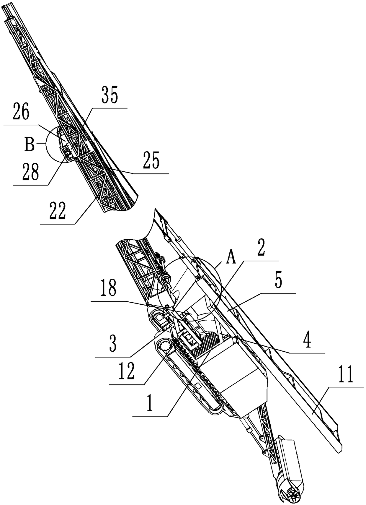
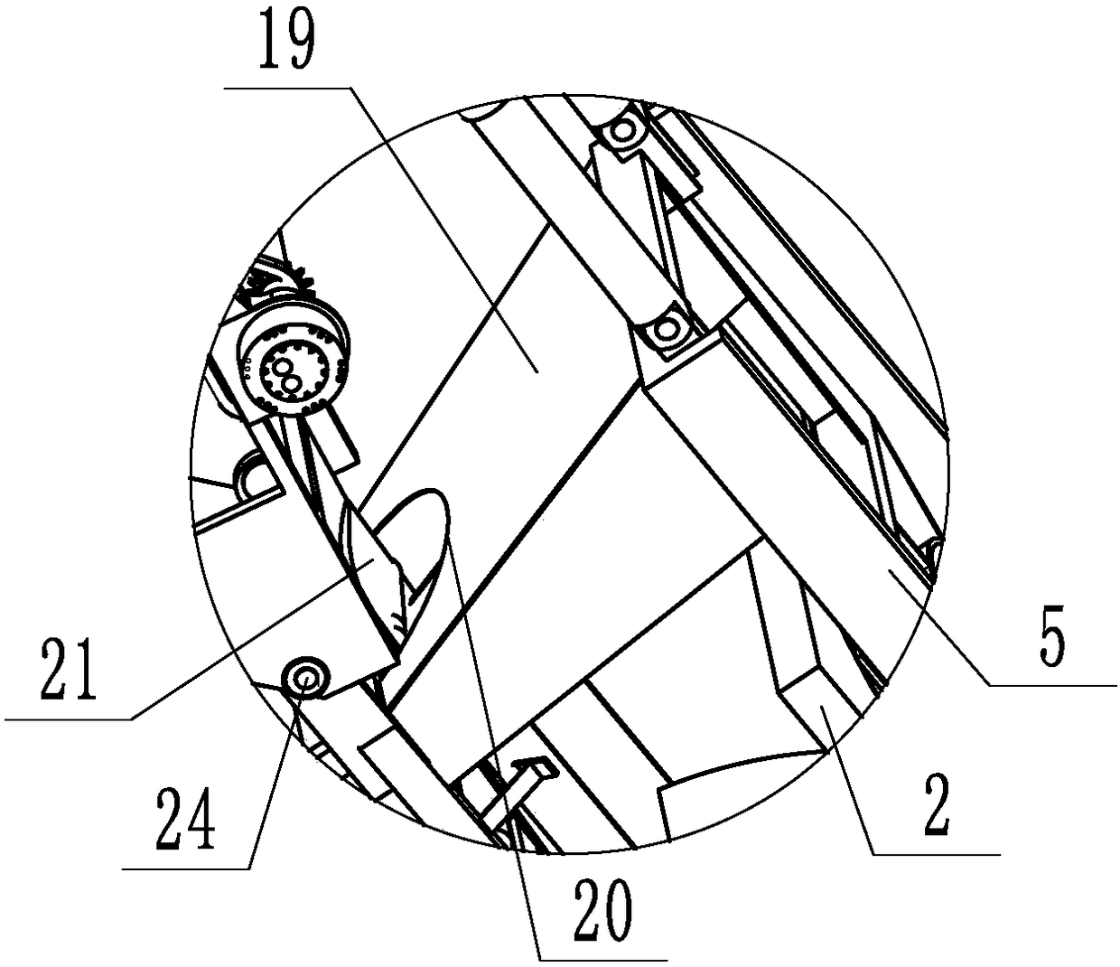
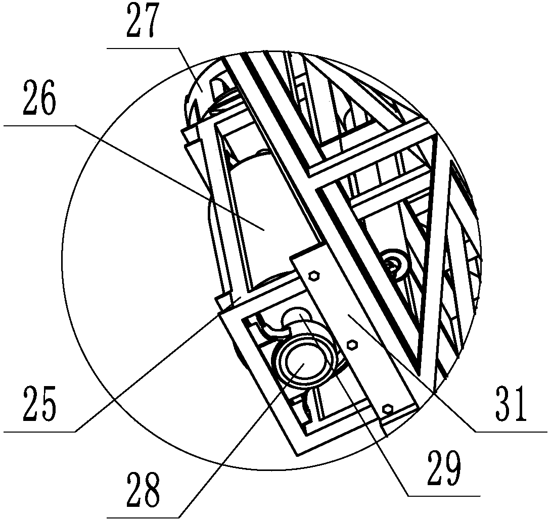
[0031] according to Figure 1 to Figure 7 As shown, a mobile automatic sand loading machine rotary mechanism includes a rotary part, a belt 21, a belt bracket 22 and a support frame 1, the belt 21 is installed in the belt bracket 22, and the belt bracket 22 is located in front of the support frame 1. The upper end of the support frame 1 is provided with an upper slewing support 2, the lower end of the support frame 1 is provided with a lower slewing support 3, the right end of the upper slewing support 2 is welded together with the main body of the support frame 1, and the upper end of the upper slewing support 2 is a flat plate. A through hole is provided at the middle position, and a support rod 4 is provided between the upper slewing support 2 and the main body of the support frame 1. The angle formed between the support rod 4 and the main body of the support frame 1 is 45°, and the upper end of the support rod 4 and the upper rotary The lower end surface of the support 2 i...


PUM


Abstract

The invention discloses a mobile automatic sand loader rotating mechanism. The mobile automatic sand loader rotating mechanism comprises a rotating part, a belt, a belt bracket and a support frame; an upper rotating support is arranged at the upper end of the support frame; a lower rotating support is arranged at the lower end of the support frame; the rotating part includes an upper rotating part and a lower rotating part; the upper rotating part is supported on the upper rotating support; the lower rotating part is supported on the lower rotating support; the upper rotating part includes an upper rotating frame and a rotating bearing I; the lower rotating part includes a lower rotating frame and a rotating bearing II; a connecting frame is arranged between the upper rotating support and the lower rotating support; the upper end of the connecting frame is connected with the upper rotating support; and the lower end of the connecting frame is connected with the lower rotating support. The mobile automatic sand loader rotating mechanism is long in key belt extension distance, large in rotating angle, stable in structure and long in service life.

Description

technical field [0001] The invention relates to the technical field of conveying machinery, in particular to a rotary mechanism of a mobile automatic sand loading machine. Background technique [0002] As a continuous material transportation method, belt transportation has the advantages of large transportation capacity, simple structure, convenient maintenance, and standardized components. It is widely used in mining, metallurgy, coal and other departments to transport loose materials or finished items. . [0003] The mobile automatic sand loading machine adopts the principle of belt transportation, which is a continuous transportation machine with belts as traction and bearing parts. The belt winds around the drive drum and various reversing drums, and the tension device gives proper tension. When working, driven by the drive device, the belt runs through the friction and tension between the drum and the belt. . The material is continuously sent to the belt and moves to...

Claims


Application Information

Patent Timeline
Patent Type & Authority Patents(China)
IPC IPC(8): B65G41/00
CPCB65G41/002B65G2201/045
Inventor 白宝军
Owner 山东大军机械有限公司
Why Eureka
Try Eureka