
Camera fixing support used for unmanned aerial vehicle

A fixed camera and unmanned aerial vehicle technology, which is applied to motor vehicles, aircraft parts, aircraft, etc., can solve the problems of cameras not working properly, unable to complete shooting tasks, and materials with good thermal insulation performance, so as to achieve simplified shooting preparations and cooling effects Visible, easy-to-operate results

Active Publication Date: 2017-02-22
GUANGZHOU HI TARGET SURVEYING INSTRUMENT CO LTD
View PDF4 Cites 2 Cited by
  • Summary
  • Abstract
  • Description
  • Claims
  • Application Information

AI Technical Summary

Problems solved by technology

The camera needs a built-in battery to supply power alone. If the camera is insufficient, it cannot complete the shooting task
[0003] Sponge, as a camera support, is widely used in the fields of drone aerial photography and surveying and mapping. A problem that cannot be avoided with sponge support cameras: the material has good thermal insulation performance and slow heat dissipation, which causes the camera to fail to work normally due to overheating.

Method used


Image

  • Camera fixing support used for unmanned aerial vehicle
  • Camera fixing support used for unmanned aerial vehicle
  • Camera fixing support used for unmanned aerial vehicle

Examples


Embodiment Construction

[0024] The present invention will be further described below in conjunction with the drawings:

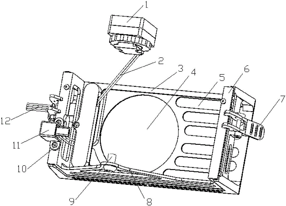
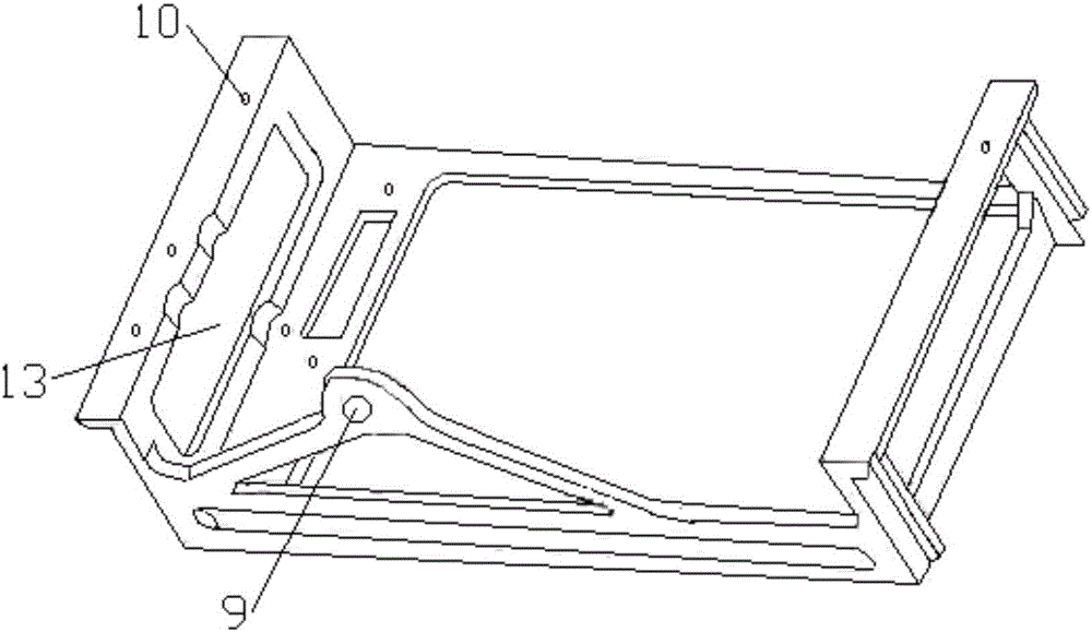
[0025] A camera fixing frame for unmanned aerial vehicles, comprising a base 3, a frame 6 installed inside the base 3, and a locking structure 7 connecting the base 3 and the frame 6; a rectangular window is opened on the front of the frame 6, and the frame 6 There are rectangular holes 13 on the left and right side walls, the top of the side wall of the frame 6 protrudes outwards, the protrusions on the top of the side wall outwards are provided with screw holes 10, and the bottom of the frame 6 is provided with a support plate 8 , The support plate 8 is provided with a camera fastening screw hole 9; the front of the base 3 is provided with a lens hole 4, the front of the base 3 is provided with an escape hole 5, and both sides of the base 3 are provided with data ports 14. A locking chuck 15 is provided on the outer sides of both sides of the base 3, and a locking structure 7 is ins...


PUM


Abstract

A camera fixing support used for an unmanned aerial vehicle comprises a base (3), a frame (6) installed on the inner side of the base (3), and locking structures (7) used for enabling the base (3) and the frame (6) to be connected. A rectangular window is formed in the front face of the frame (6). Rectangular holes (13) are formed in the left side wall and the right side wall of the frame (6) correspondingly. The top ends of the side walls of the frame (6) protrude outwards. Screw holes (10) are formed in protrusions protruding outwards from the top ends of the side walls of the frame (6). A support plate (8) is arranged at the bottom of the frame (6) and provided with a camera fastening screw hole (9). A camera lens hole (4) and receding holes (5) are formed in the front face of the base (3). Data interfaces (14) are arranged on the two sides of the base (3) correspondingly. Locking clamp heads (15) are arranged on the outer sides of the two sides of the base (3) correspondingly, and the locking structures (7) are installed in the positions of the locking clamp heads (15) correspondingly.

Description

Technical field [0001] The invention belongs to the field of aerial surveying and mapping and data collection, and specifically relates to a camera fixing frame for unmanned aerial vehicles. Background technique [0002] At present, the drone is equipped with a camera. When completing aerial photography, the camera is usually placed in a hollow sponge that is tightly matched with it. The elasticity of the sponge is used to offset the various effects of the drone during take-off, landing and flight. Bumps and shakes to ensure the camera's shooting effect and the camera from impact damage. The camera needs a built-in battery to supply power separately. If the camera has insufficient power, it will not be able to complete the shooting task. [0003] As a camera support, sponge is widely used in the field of drone aerial photography and surveying. An unavoidable problem with the sponge supporting the camera: the material has good thermal insulation performance and slow heat dissipatio...

Claims


Application Information

Patent Timeline
Patent Type & Authority Applications(China)
IPC IPC(8): B64D47/08B64C39/02
CPCB64C39/02B64D47/08
Inventor 李白王少海时颖
Owner GUANGZHOU HI TARGET SURVEYING INSTRUMENT CO LTD
Learn More