A variable grazing angle ejection tandem wing flying robot
A flying robot, a variable technology, applied in the directions of aircraft, motor vehicles, wing adjustment, etc., can solve the problem that the two rear folding wings 3 cannot be unfolded separately, the attitude control of the flying robot cannot be realized, and the front folding wings 2 cannot be unfolded separately, etc. problems, to achieve the effect of facilitating high-speed flight, simplifying the folding structure and tail rudder structure, and light weight
- Summary
- Abstract
- Description
- Claims
- Application Information
AI Technical Summary
Problems solved by technology
Method used
Image
Examples
specific Embodiment approach 1
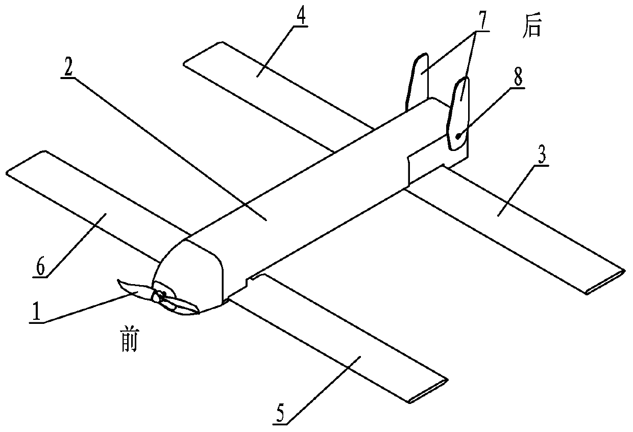
[0019] Specific implementation mode one: combine Figure 1 to Figure 4 Describe this embodiment, this embodiment comprises folding propeller 1, fuselage 2, left rear wing 3, right rear wing 4, left front wing 5, right front wing 6, two vertical empennages 7, two vertical empennage pin shafts 8 and four A rotating hinge 9, folding propeller 1 is installed on the head of fuselage 2, arranges like this to be conducive to the ejection launch of flying robot, left front wing 5 and right front wing 6 are symmetrically arranged on both sides of fuselage 2 front ends, left rear wing 3 and The right rear wing 4 is symmetrically arranged on both sides of the rear end of the fuselage 2, and the left front wing 5, the right front wing 6, the left rear wing 3 and the right rear wing 4 are respectively hinged with their corresponding rotary hinges 9, and each rotary hinge 9 is connected to the fuselage. 2. The corresponding steering gear is connected inside (the hinge 9 is driven by the ste...
specific Embodiment approach 2
[0021] Specific implementation mode two: combination Figure 4 The present embodiment will be described. The left front wing 5 and the right front wing 6 of the present embodiment are rotated forward by 0° to 90° from a position parallel to the fuselage 2 . Such an arrangement can ensure rapid and accurate deployment of the wings of the flying robot and that the front wings can only be swept back during flight, thereby reducing the complexity of the control of the flying robot. Other components and connections are the same as those in the first embodiment.
specific Embodiment approach 3
[0022] Specific implementation mode three: combination figure 2 The present embodiment will be described. The left rear wing 3 and the right rear wing 4 of the present embodiment are rotated backward by 0° to 90° from a position parallel to the fuselage 2 . This arrangement can ensure that the wings of the flying robot can be deployed quickly and accurately, and that the rear wing can only be swept forward during flight, thereby reducing the complexity of the control of the flying robot. Other components and connections are the same as those in the second embodiment.
[0023] Working principle of the present invention:
[0024] (1) Before the flying robot ejects and takes off, each wing rotates to a position parallel to the fuselage 2, see figure 1 and figure 2 ;
[0025] (2) After the flying robot is ejected, the left front wing 5 and the right front wing 6 are fully deployed after turning forward 90° under the driving of the steering gear; the left rear wing 3 and the ...
PUM
 Abstract
Description
Claims
Application Information
 - R&D Engineer
- R&D Manager
- IP Professional
- Industry Leading Data Capabilities
- Powerful AI technology
- Patent DNA Extraction
Browse by: Latest US Patents, China's latest patents, Technical Efficacy Thesaurus, Application Domain, Technology Topic, Popular Technical Reports.
© 2024 PatSnap. All rights reserved.Legal|Privacy policy|Modern Slavery Act Transparency Statement|Sitemap|About US| Contact US: help@patsnap.com


