
Multifunctional charging pile device for electric automobiles

A technology for electric vehicles and charging piles, which is applied in the direction of electric vehicle charging technology, electric vehicles, charging stations, etc., and can solve problems such as potential safety hazards and damage

Inactive Publication Date: 2017-02-22
YANTAI POWER SUPPLY COMPANY OF STATE GRID SHANDONG ELECTRIC POWER +1
View PDF7 Cites 13 Cited by
  • Summary
  • Abstract
  • Description
  • Claims
  • Application Information

AI Technical Summary

Problems solved by technology

[0002] Existing charging piles are usually hung on the wall or directly installed on the ground, which are easy to be damaged when external forces collide, especially when used in underground garages, they are prone to failure due to water accumulation and other problems, posing safety hazards

Method used


Image

  • Multifunctional charging pile device for electric automobiles
  • Multifunctional charging pile device for electric automobiles

Examples


Embodiment 1

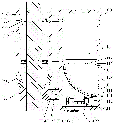
[0021] In order to facilitate the installation of the terminal, in this embodiment, preferably, a through hole is provided on the lower end surface of the box body 101, and a terminal post 116 is provided above the through hole, and the terminal 114 is installed On the terminal post 116, an end cap 117 for closing the through hole is arranged inside the through hole. When charging is required, the power cord is plugged into the terminal. Since the terminal is located on the terminal, the terminal can be placed inside the box, so as to avoid the risk of safety accidents caused by the exposure of the existing terminal. The problem is that due to the end cover structure, the through hole can be closed when necessary, thereby avoiding the exposure of the terminal, making it safer and more reliable.

[0022] Further preferably, in order to prevent accumulated water from entering the box, in this embodiment, a central shaft 118 is provided inside the through hole, and the middle par...

Embodiment 2

[0025] In this embodiment, in order to improve the stability of the overall structure, a reinforcement structure is provided under the fixed sleeve to support the fixed sleeve and the box. Preferably, a support sleeve is provided under the fixed sleeve 103 123. Fix the fixed sleeve on the rod body through the pressure rod to keep the fixed sleeve stable, and then install the support sleeve on the rod body below the fixed sleeve, and the support sleeve 123 faces the box body 101 An opening is provided on one side to facilitate the adjustment of the tightness of the support sleeve, and a mounting plate 124 is provided on the opening, so that two mutually parallel mounting plates are arranged on the opening for fixing the support sleeve on the box. On the body, two positioning plates 125 are arranged on the end surface of the side of the box body 101 facing the support sleeve 123, so that the two positioning plates are parallel to each other, and there is formed between the two po...


PUM


Abstract

The invention discloses a multifunctional charging pile device for electric automobiles. The multifunctional charging pile device for electric automobiles comprises a box and a charging pile body arranged on the inner side of the box, a fixing casing pipe is arranged on one side of the box, two sets of parallel pressing rods are arranged on the side, close to the box, of the fixing casing pipe, the pressing rods are parallel to the end face of the side, close to the fixing casing pipe, of the box, two symmetrical strip-shaped holes are formed in the fixing casing pipe, the two ends of the pressing rods are connected to the inner sides of the strip-shaped holes in an inserted mode respectively, screws are arranged on the inner wall of the box, and the screws penetrate through the inner wall of the box and are fixed to the pressing rods through nuts. The multifunctional charging pile device for electric automobiles can relieve problems in the prior art, the charging pile can be conveniently installed in a hung mode to be separated from the ground, and thus it can be avoided that the charging pile is damaged by collision or water accumulation.

Description

technical field [0001] The invention relates to a multifunctional electric vehicle charging pile device. Background technique [0002] Existing charging piles are usually hung on the wall or directly installed on the ground, which are easy to be damaged when external forces collide, especially when used in underground garages, they are prone to malfunction due to water accumulation and other problems, posing safety hazards. Contents of the invention [0003] The purpose of the present invention is to provide a multifunctional electric vehicle charging pile device, which can improve the problems existing in the prior art, and can conveniently hang and install the charging pile so that it is separated from the ground, thereby avoiding collisions or accumulation of water on the charging pile. damage. [0004] The present invention is realized through the following technical solutions: [0005] A multifunctional electric vehicle charging pile device, comprising a box body an...

Claims


Application Information

Patent Timeline
Patent Type & Authority Applications(China)
IPC IPC(8): B60L11/18
CPCB60L53/31Y02T10/70Y02T10/7072Y02T90/12
Inventor 安好好王爱心丛旭日王芳郑伟刘国强刘扬张文韬王新国李天辉贾文嘉姜玉玺王万明于世利尹潇
Owner YANTAI POWER SUPPLY COMPANY OF STATE GRID SHANDONG ELECTRIC POWER
Learn More