
Rapid cleaning and drying equipment for bearings

A kind of drying equipment and fast technology, applied in the field of mechanical equipment, can solve the problems of increased labor intensity, incomplete cleaning of bearings, and large space occupation, etc., to achieve good cleaning effect, good effect, and reduced space occupation

Active Publication Date: 2017-02-22
HUNAN MEIBEIDA TECH CO LTD
View PDF8 Cites 11 Cited by
  • Summary
  • Abstract
  • Description
  • Claims
  • Application Information

AI Technical Summary

Problems solved by technology

[0002] With the continuous development of society, people continue to invent and innovate, and various types of machinery are continuously invented. As an important part of mechanical products, bearings have continuously improved requirements for bearings, especially the cleaning and drying of bearings. Therefore, a quick cleaning and drying equipment for bearings came into being. There are many types of such devices on the market today, but there are still some problems. Most of these devices on the market today are to add cleaning liquid first and then use spray cleaning. In this way, the cleaning fluid may be washed away during the cleaning process, the cleaning of the bearing is not thorough, and a lot of water resources are wasted
At the same time, after the bearing is cleaned, it is necessary to manually transfer the bearing to the drying equipment, which increases the labor intensity and takes up a lot of space for multiple machines

Method used


Image

  • Rapid cleaning and drying equipment for bearings
  • Rapid cleaning and drying equipment for bearings

Examples


Embodiment Construction

[0013] The following will clearly and completely describe the technical solutions in the embodiments of the present invention with reference to the accompanying drawings in the embodiments of the present invention. Obviously, the described embodiments are only some, not all, embodiments of the present invention. Based on the embodiments of the present invention, all other embodiments obtained by persons of ordinary skill in the art without making creative efforts belong to the protection scope of the present invention.

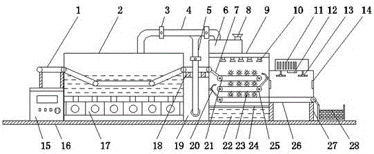
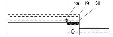
[0014] refer to Figure 1-2 , an embodiment provided by the present invention: a bearing quick cleaning and drying equipment, including an ultrasonic cleaning box 2, a cleaning room 9, an air-drying drying room 14 and a filter room 19, and an ultrasonic cleaning box 2 is installed at one end above the bottom plate 16 , and the bottom end of the ultrasonic cleaning box 2 is equipped with an ultrasonic generator 17, the liquid level of the liquid in the ultrason...


PUM


Abstract

The invention discloses rapid cleaning and drying equipment for bearings. The equipment comprises an ultrasonic cleaning box, a cleaning chamber, an air-drying chamber and a filtering chamber; the ultrasonic cleaning box is mounted at one end above a bottom plate; an ultrasonic generator is mounted at the bottom end inside the ultrasonic cleaning box; a control box is mounted on one side of the bottom end of the ultrasonic cleaning box; the filtering chamber is mounted on the other side of the bottom end of the ultrasonic cleaning box; the top end of the filtering chamber communicates with one side of the bottom end of the ultrasonic cleaning box through a water outlet; and a storage tank is mounted on one side of the bottom end of a second supporting column. The ultrasonic cleaning box is mounted on the equipment, the bearings are cleaned with ultrasonic waves, the cleaning effect is good, use of a cleaning agent is avoided, the equipment is environment-friendly, the cleaning chamber and the air-drying chamber are arranged on one side of the ultrasonic cleaning box and are connected through a conveying track, the labor intensity is reduced, and the occupied space of the equipment is reduced.

Description

technical field [0001] The invention relates to the technical field of mechanical equipment, in particular to a quick cleaning and drying equipment for bearings. Background technique [0002] With the continuous development of society, people continue to invent and innovate, and various types of machinery are continuously invented. As an important part of mechanical products, bearings have continuously improved requirements for bearings, especially the cleaning and drying of bearings. Therefore, a quick cleaning and drying equipment for bearings came into being. There are many types of such devices on the market today, but there are still some problems. Most of these devices on the market today are to add cleaning liquid first and then use spray cleaning. In this way, the cleaning liquid may be washed away during the cleaning process, the cleaning of the bearing is not thorough, and a large amount of water resources are wasted. At the same time, after the bearing is cleaned...

Claims


Application Information

Patent Timeline
IPC IPC(8): B08B3/12B08B3/02B08B1/02B08B3/14F26B21/00F26B23/04
CPCF26B21/004F26B23/04B08B3/022B08B3/123B08B3/14B08B1/20
Inventor 赵青华
Owner HUNAN MEIBEIDA TECH CO LTD
Learn More