Lasso driving mechanism with two degrees of freedom
A technology of transmission mechanism and degrees of freedom, applied in manipulators, manufacturing tools, passive exercise equipment, etc., can solve the problems of heavy overall weight of the exoskeleton wrist joint and small joint motion range, and achieve the effect of stable and reliable transmission.
- Summary
- Abstract
- Description
- Claims
- Application Information
AI Technical Summary
Problems solved by technology
Method used
Image
Examples
specific Embodiment approach 1
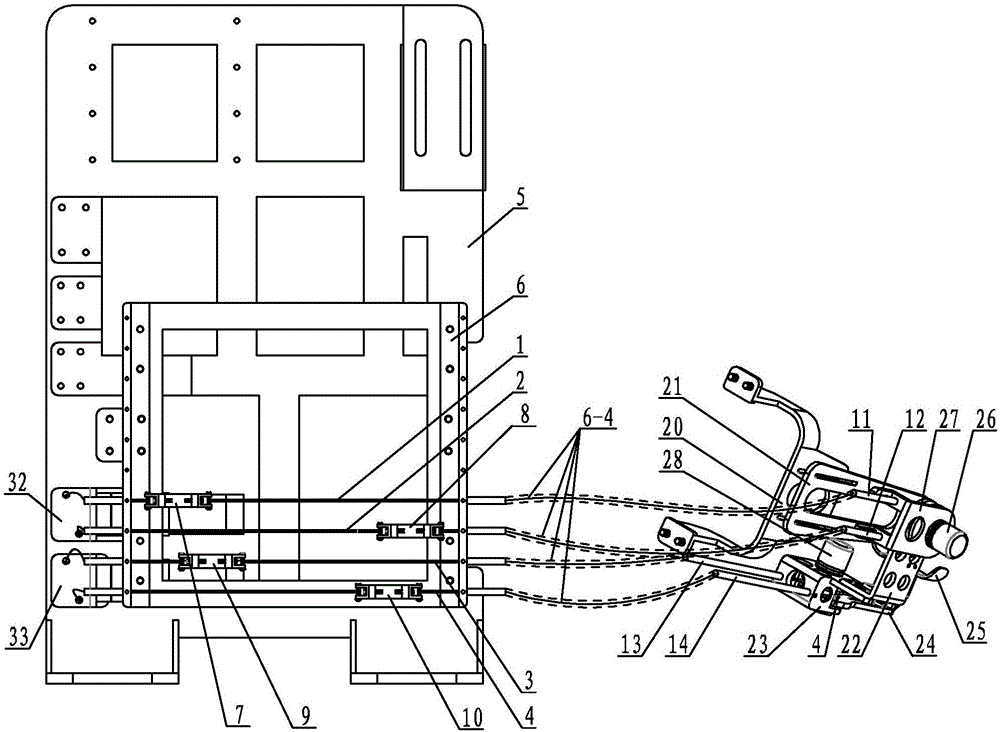
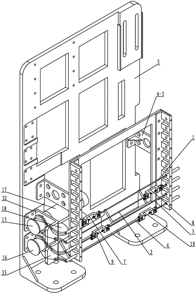
[0017] Specific implementation mode one: combine Figure 1 to Figure 7 Describe this embodiment, this embodiment includes the first rope 1, the second rope 2, the third rope 3, the fourth rope 4, the back plate 5, the groove base plate 6, the first pretensioning device 7, the second pretensioning device 8. The third pretensioning device 9, the fourth pretensioning device 10, the first rope sheath 11, the second rope sheath 12, the third rope sheath 13, the fourth rope sheath 14, the first output wheel 15, the second output wheel 16. First motor 17, second motor 18, joint shaft 19, wrist-elbow connector 20, forearm part 21, wrist radial deviation / ulnar deviation movement part 22, wrist flexion and extension movement part 23, palm part 24, palm rest Component 25, the first encoder 26, the first encoder mounting frame 27, the second encoder 28, the first bearing 29, the second bearing 30, the third bearing 31, one end of the forearm component 21 is connected with the wrist and el...
specific Embodiment approach 2
[0018] Specific implementation mode two: combination Image 6 This embodiment will be described. In this embodiment, the axis of the second installation shaft head 22-1 coincides with the axis of the first installation shaft head 21-1. Other components and connections are the same as those in the first embodiment.
specific Embodiment approach 3
[0019] Specific implementation mode three: combination figure 2 Describe this embodiment, this embodiment is that the first pretensioning device 7, the second pretensioning device 8, the third pretensioning device 9 and the fourth pretensioning device 10 are all composed of a U-shaped seat 7-1, a left U-shaped connector 7-2, right U-shaped connector 7-3, left pre-tightening bolt 7-4, right pre-tightening bolt 7-5, left screw 7-6, right screw 7-7, left nut 7-8 and right nut 7 -9, the U-shaped opening of the U-shaped seat 7-1 is set forward, the left side of the U-shaped seat 7-1 is provided with a left threaded hole 7-1-1, and the right side of the U-shaped seat 7-1 There is a right threaded hole 7-1-2, the left U-shaped connector 7-2 and the right U-shaped connector 7-3 are symmetrically arranged on the left and right ends of the U-shaped seat 7-1, and the left U-shaped connector 7-2 and the U-shaped opening of the right U-shaped connector 7-3 are respectively facing the out...
PUM
 Abstract
Description
Claims
Application Information
 - R&D Engineer
- R&D Manager
- IP Professional
- Industry Leading Data Capabilities
- Powerful AI technology
- Patent DNA Extraction
Browse by: Latest US Patents, China's latest patents, Technical Efficacy Thesaurus, Application Domain, Technology Topic, Popular Technical Reports.
© 2024 PatSnap. All rights reserved.Legal|Privacy policy|Modern Slavery Act Transparency Statement|Sitemap|About US| Contact US: help@patsnap.com


