
Mechanical keyboard dust sucking working platform

A technology for mechanical keyboards and working platforms, which is applied to vacuum cleaners, vacuum cleaner storage devices, cleaning equipment, etc., can solve the problems of time-consuming and laborious, mechanical keyboards are not waterproof, dust and stains are difficult to remove, and achieve good cleaning effect and practical effect. High cleaning efficiency

Active Publication Date: 2017-02-22
DONGGUAN WULIAN ELECTRONICS TECH
View PDF6 Cites 1 Cited by
  • Summary
  • Abstract
  • Description
  • Claims
  • Application Information

AI Technical Summary

Problems solved by technology

[0007] (4) After cleaning, put the keycap on the side and let it dry naturally (be sure to dry it thoroughly without moisture, the mechanical keyboard is not waterproof, if water enters, it will cause damage to the mechanical shaft or circuit)
[0009] The above method is time-consuming and labor-intensive, but the reason why the keycaps are pulled out one by one by the above method is that the structure of the mechanical keyboard keys is relatively complicated, and it is more difficult to remove dust and stains remaining in the gaps of the mechanical keyboard keys. The present invention provides a An automatic cleaning method specifically for mechanical keyboards, the beneficial effects of which are:

Method used


Image

  • Mechanical keyboard dust sucking working platform
  • Mechanical keyboard dust sucking working platform
  • Mechanical keyboard dust sucking working platform

Examples


Embodiment 1

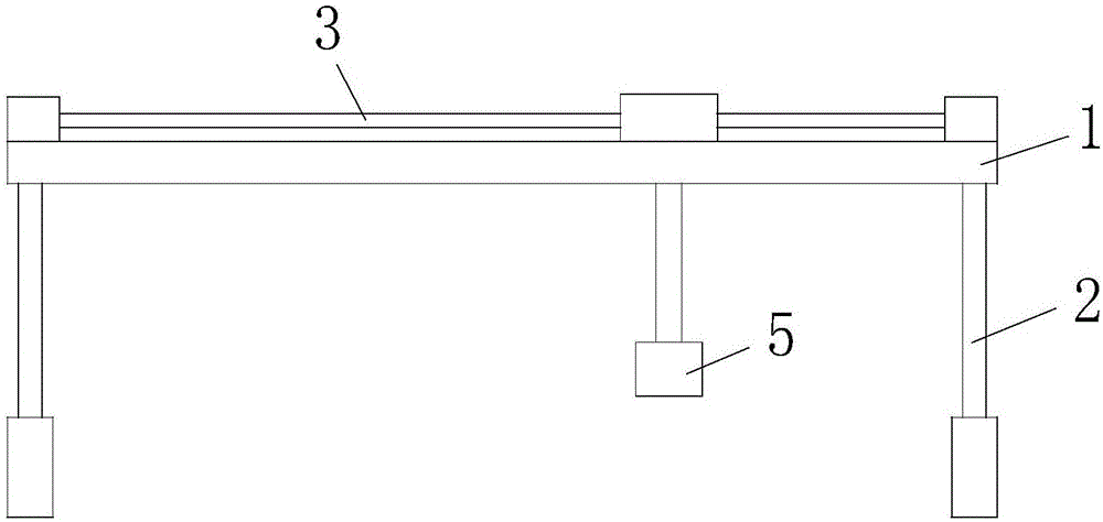
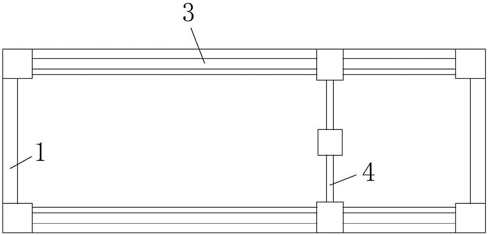
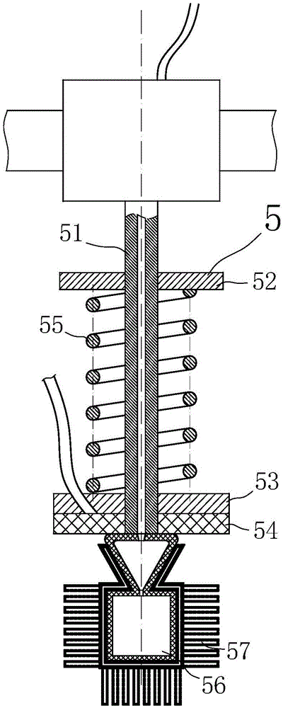
[0043] like figure 1 , figure 2 , image 3 , Figure 4 , Figure 5 , Image 6 and Figure 7 As shown, a mechanical keyboard vacuuming work platform according to the present invention includes a main frame 1, a bottom lifting device 2, a left and right moving device 3 and a front and rear moving device 4. The main frame 1 is a square frame structure as a whole, and the main frame A PLC controller is installed on the frame 1, and the PLC controller is used to control the work of all electrical components and pneumatic components in the present invention. The bottom lifting device 2 is installed at the four corners of the main frame 1 bottom, and the top of the bottom lifting device 2 is connected to the main frame. The frame 1 is hinged, and the bottom lifting device 2 can be a cylinder, which is used to lift the main frame 1, so that the present invention can adapt to the needs of mechanical keyboards of different heights, and each part of the bottom lifting device 2 can ...

Embodiment 2

[0051] The difference between embodiment 2 and embodiment 1 is that the cleaning cavity 56 is a cubic cavity structure as a whole, because the key gaps of non-mechanical keyboards are generally cubic structure gaps, so this design enables the present invention to meet general conventional non-standard requirements. mechanical keyboard.


PUM


Abstract

The invention relates to the field of computer cleaning, and particularly relates to a mechanical keyboard dust sucking working platform which comprises a main rack, a bottom lifting device, a left-to-right movement device and a front-to-back movement device, and further comprises a cleaning main body, wherein the cleaning main body comprises a cleaning main tube, a top fixing plate, a lower sliding plate, top brush sponge, a spring, a cleaning cavity and a cleaning terminal, wherein the cleaning cavity comprises an upper cavity and a lower cavity; the upper cavity is of a conical cavity structure of which the upper part is large and the lower part is small overall; the lower cavity is of a cube cavity structure overall; the cleaning terminal comprises a dust sucking cavity, a dust sucking tube and a dust sucking hole. The mechanical keyboard dust sucking working platform is high in cleaning and brushing efficiency, moreover, due to the structural design of the upper cavity and the lower cavity, gaps of a mechanical keyboard can be specifically cleaned according to the shapes of the gaps of the mechanical keyboard, and the mechanical keyboard dust sucking working platform is relatively applicable to cleaning on side walls of the mechanical keyboard, therefore, the mechanical keyboard dust sucking working platform is relatively good in cleaning effect.

Description

technical field [0001] The invention relates to the field of computer cleaning, in particular to a mechanical keyboard dust-absorbing work platform. Background technique [0002] Now more and more people choose to use notebook computers for office work, and the most frequently used one is the notebook keyboard. The keyboard is easy to break if it accumulates a lot of dust. If the desktop keyboard is broken, you can replace it, but it will increase unnecessary costs. , and it is very troublesome to change the keyboard of the notebook, so after normal use, if you find that the keyboard is dusty, you can find a way to clean the dust in the gaps of the keyboard, and clean it frequently to maintain the health and longevity of the keyboard. [0003] Compared with ordinary keyboards, mechanical keyboards feel better, are more expensive, and are relatively troublesome to maintain. The existing methods for cleaning dust and stains on the mechanical keyboard are mainly: [0004] (1)...

Claims


Application Information

Patent Timeline
Patent Type & Authority Applications(China)
IPC IPC(8): A47L7/00A47L9/00
CPCA47L7/0057A47L9/0009
Inventor 李霞林
Owner DONGGUAN WULIAN ELECTRONICS TECH
Learn More