Electromagnetic braking or coupling device having damping means for improved noise reduction

A clutch device, electromagnetic brake technology, applied in the direction of magnetic drive clutch, non-mechanical drive clutch, clutch, etc., can solve the problem of electromagnetic brake or clutch device torque characteristics and negative effects of switching characteristics and other problems

Active Publication Date: 2017-02-15
KENDRION VILLINGEN GMBH
View PDF8 Cites 5 Cited by
  • Summary
  • Abstract
  • Description
  • Claims
  • Application Information

AI Technical Summary

Problems solved by technology

[0005] A problem with hitherto known damping devices in electromagnetic brake or clutch devices is the fact that the provided damping devices often have a negative influence on the torque behavior and switching behavior of the electromagnetic brake or clutch device

Method used


Image

  • Electromagnetic braking or coupling device having damping means for improved noise reduction
  • Electromagnetic braking or coupling device having damping means for improved noise reduction
  • Electromagnetic braking or coupling device having damping means for improved noise reduction

Examples


Embodiment Construction

[0028] In the following drawings, unless otherwise specified, the reference numerals denote the same components with the same meaning.

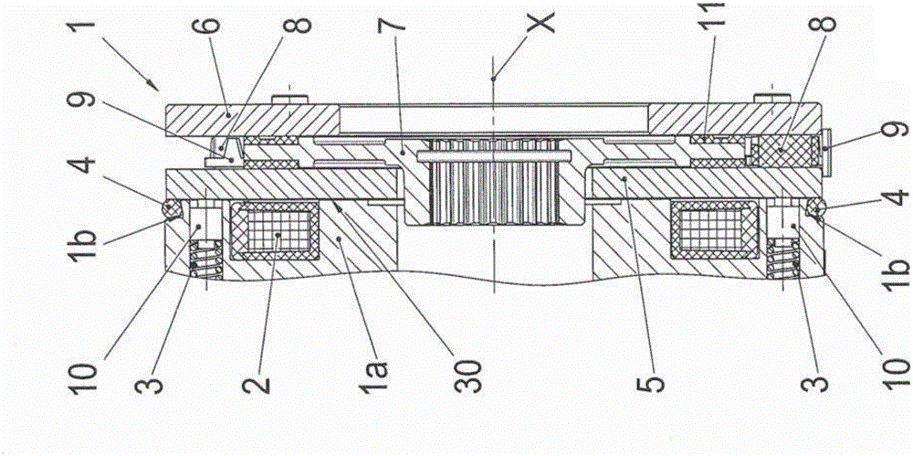
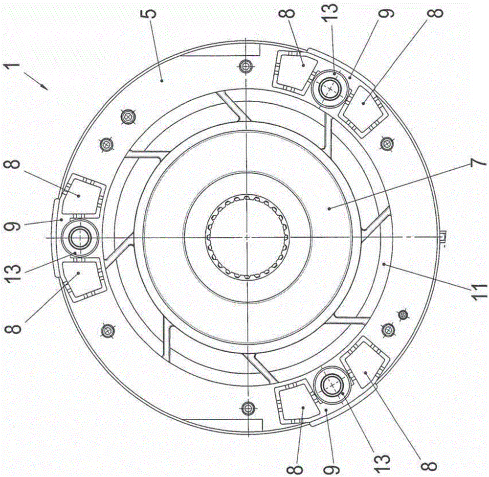
[0029] exist figure 1 shows a longitudinal section of a spring pressure brake, which is known per se, including a special damping element to be described in more detail. The spring pressure brake is designated with the reference numeral 1 and has a housing 1 a in which an exciter coil 2 is positioned in a conventional manner. The spring pressure brake 1 also has an armature disk 5 which is axially displaceable along the center axis X of the spring pressure brake 1 . At a predetermined distance to the right of the armature disk 5 there is a mounting surface 6 or a flange which can be part of a machine element or a wall element or the like on which the spring pressure brake 1 is mounted. Between the armature disk 5 and the mounting surface 6 is positioned in a known manner a friction disk 7, also called a brake or clutch disk, which is non-ro...


PUM


Abstract

The invention relates to an electromagnetic braking or coupling device (1), comprising an electromagnetically actuatable displacement unit for providing a force on at least one brake disk or coupling disk (7) and comprising damping means (4, 8) for noise reduction. One or more damping elements (4, 8) made of a viscoelastic plastic material are provided as damping means. In the event of a force load within a time window of less than approximately 2 seconds and at a room temperature approximately between 20 DEG C and 25 DEG C, the viscoelastic plastic material has an over-stress of no less than approximately 10%, preferably no less than approximately 30%, in relation to an equilibrium stress of the viscoelastic plastic material.

Description

technical field [0001] The invention relates to an electromagnetic brake or clutch arrangement having an electromagnetically actuatable adjusting unit for supplying force to at least one brake or clutch disk and having an attenuation device for reducing noise. Background technique [0002] When operating an electromagnetic brake or clutch device, undesired rattling noises and undesired vibrations often occur when mechanical elements come into contact with each other. At this time, two kinds of interference noises are first observed. For one, a so-called "attraction noise" is generated during operation, when the armature disk is attracted against the coil former and thus against the housing, and thus usually steel-on-steel. At this time, the attraction of the armature disc is usually caused by energizing the coil. In addition, there is the so-called "breakaway noise", where the armature disc is pressed against the brake motor, for example by means of spring pressure. That ...

Claims


Application Information

Patent Timeline
IPC IPC(8): F16D59/02F16D27/14F16F1/36
CPCF16D59/02F16D27/112F16D65/0006F16D27/14F16F1/3605
Inventor 尤韦·格纳尤特罗兰·本兹
Owner KENDRION VILLINGEN GMBH
Why Eureka
Try Eureka