
Control and protection switchgear

A technology for protection switches and electrical appliances, which is applied to protection switches, components of protection switches, and operation/release mechanisms of protection switches. Strong, lower airflow temperature, stable and firm structure

Active Publication Date: 2019-01-18
浙江新控电气科技有限公司
View PDF6 Cites 0 Cited by
  • Summary
  • Abstract
  • Description
  • Claims
  • Application Information

AI Technical Summary

Problems solved by technology

[0002] At present, the control and protection switching devices provided on the market generally include a base module, an electromagnet module, an operation module and an auxiliary module. The electromagnet module and the operation module are directly inserted into the base module, and the structural stability is not good. There are usually two modules, most of which are set separately, which makes the overall structure more complicated and the volume is larger, and the auxiliary module is cumbersome to drive. In addition, the above-mentioned control and protection switching devices also have the following main disadvantages: 1. Although the arc extinguishing chamber It can discharge hot air, but it is easy to generate arc, and the distance of arc spray is large, which is easy to cause three-phase short circuit; 2. There is a pull-out plastic mounting plate on the bottom of the base, which is used to install on other equipment (such as distribution box, power distribution cabinet, etc.), but the structure is poor, and it is easy to be damaged by external force, which will cause the control and protection switch to fall off; Install the cover plate to limit the contact bridge to prevent the elastic force from ejecting the contact bridge from the base. The assembly process of the contact device with this structure is cumbersome and inconvenient to maintain; 4. The spring is in direct contact with the contact bridge. When the current passes through the contact bridge during work , the contact bridge is easy to generate high temperature, which will damage the spring and make it invalid; 5. The coil skeleton is an assembled structure, which is complicated in structure and inconvenient to process. In addition, the coil suction piece is riveted on the iron core by rivets, which is difficult to disassemble and is not conducive to maintenance.

Method used


Image

  • Control and protection switchgear
  • Control and protection switchgear
  • Control and protection switchgear

Examples


Embodiment Construction

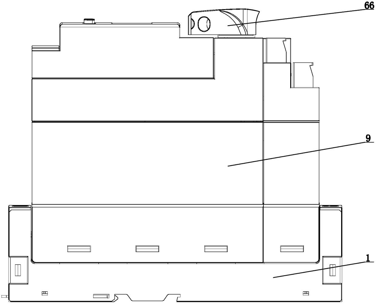
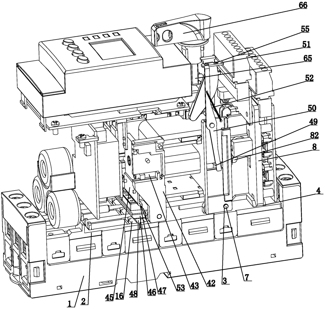
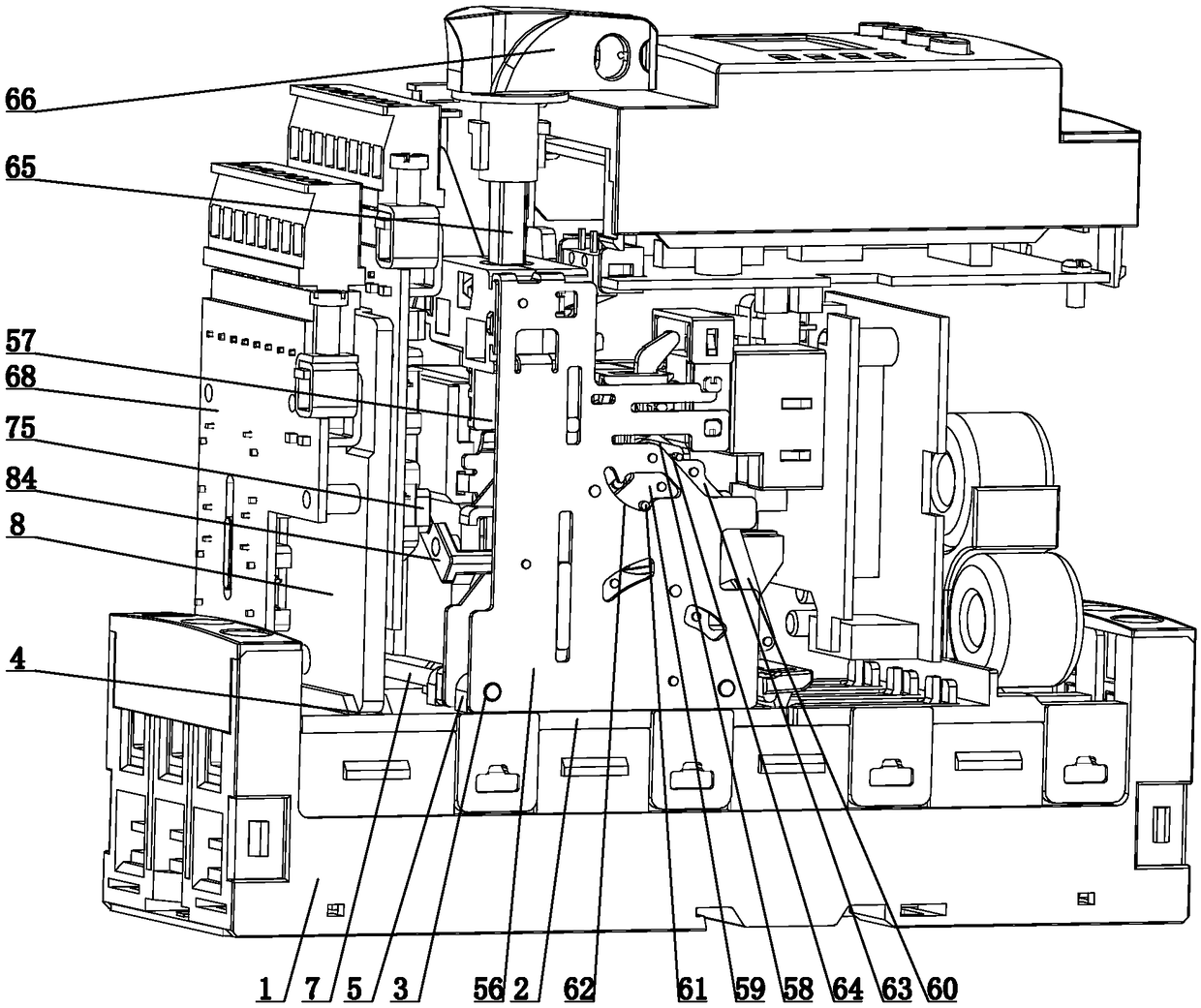
[0040] Referring to the above-mentioned drawings, the control and protection switching device provided by the present invention includes a base module and an electromagnet module, an operation module and an auxiliary module arranged on the base module. The base module includes a base 1 and a The cover plate 2, the cover plate 2 is fastened on the base 1, both sides of the electromagnet module and the operation module have a plurality of coaxial first through holes 3, and the cover plate 2 is provided with a slot 4 and a plurality of The mounting seat 5 that can cooperate with the first through hole 3 is provided with a second through hole 6 aligned with the first through hole 3 on the mounting seat 5, and the first through hole 3 and the second through hole 6 are fixed by a pin shaft 7, The auxiliary module includes a support plate 8 that can be inserted into the slot 4. The electromagnet module, the operation module and the auxiliary module are provided with a casing 9 on the ...


PUM


Abstract

The invention discloses a control and protection switch electric appliance. The electric appliance comprises a pedestal module, an electromagnet module, an operation module and an auxiliary module, wherein the electromagnet module, the operation module and the auxiliary module are arranged on the pedestal module. The electric appliance is characterized in that the pedestal module includes a pedestal and a cover plate which is detachably arranged on the pedestal; two sides of the electromagnet module and the operation module are provided with a plurality of first through holes which are coaxially arranged; the cover plate is provided with a slot and a plurality of installation seats which can be cooperated with the first through holes; the installation seats are provided with second through holes aligning at the first through hole; the first through hole and the second through holes are fixed through pins; the auxiliary module includes a support plate which can be inserted into the slot; peripheries of the electromagnet module, the operation module and the auxiliary module are provided with shells; and the shell is detachably arranged on the pedestal. By using the control and protection switch electric appliance provided in the invention, the structure is simple and compact, a three phase short circuit is not easy to generate, stability is good, assembling and maintenance are convenient and a service life is long.

Description

technical field [0001] The invention relates to a control and protection switching device. Background technique [0002] At present, the control and protection switching devices provided on the market generally include a base module, an electromagnet module, an operation module and an auxiliary module. The electromagnet module and the operation module are directly inserted into the base module, and the structural stability is not good. There are usually two modules, most of which are set separately, which makes the overall structure more complicated and the volume is larger, and the auxiliary module is cumbersome to drive. In addition, the above-mentioned control and protection switching devices also have the following main disadvantages: 1. Although the arc extinguishing chamber It can discharge hot air, but it is easy to generate arc, and the arc spraying distance is large, which is easy to cause three-phase short circuit; 2. There is a pull-out plastic mounting plate on t...

Claims


Application Information

Patent Timeline
Patent Type & Authority Patents(China)
IPC IPC(8): H01H71/02H01H71/46H01H73/18
CPCH01H71/0207H01H71/46H01H73/18
Inventor 张彭春刘超儒杨辉吴杰江维强李里
Owner 浙江新控电气科技有限公司
Learn More