
Method and system for determining displacement pressure in constant-rate and constant-pressure chemical flooding experiments

A displacement pressure and determination method technology, applied to scientific instruments, instruments, measuring devices, etc., can solve problems such as inability to determine displacement pressure, inability to achieve on-site pressure, and inability to guide mine practice

Active Publication Date: 2019-01-04
NORTHEAST GASOLINEEUM UNIV
View PDF4 Cites 0 Cited by
  • Summary
  • Abstract
  • Description
  • Claims
  • Application Information

AI Technical Summary

Problems solved by technology

The constant pressure experiment guarantees the constant pressure simulation, but how much pressure should be used to match the field is also a problem, because the indoor core is short, the pressure is too low, the displacement fluid cannot advance, and the pressure is too high, the displacement fluid breaks through too quickly , with the simulated distortion of the live
[0004] Therefore, the defect in the prior art is that the conversion of the on-site pressure and the pressure of the actual indoor experiment cannot be realized, that is, an actual displacement pressure cannot be determined, and then the results of the constant velocity experiment and the constant pressure experiment are not comparable, and it is impossible to compare Mine practice serves as a guide

Method used


Image

  • Method and system for determining displacement pressure in constant-rate and constant-pressure chemical flooding experiments
  • Method and system for determining displacement pressure in constant-rate and constant-pressure chemical flooding experiments
  • Method and system for determining displacement pressure in constant-rate and constant-pressure chemical flooding experiments

Examples


Embodiment 1

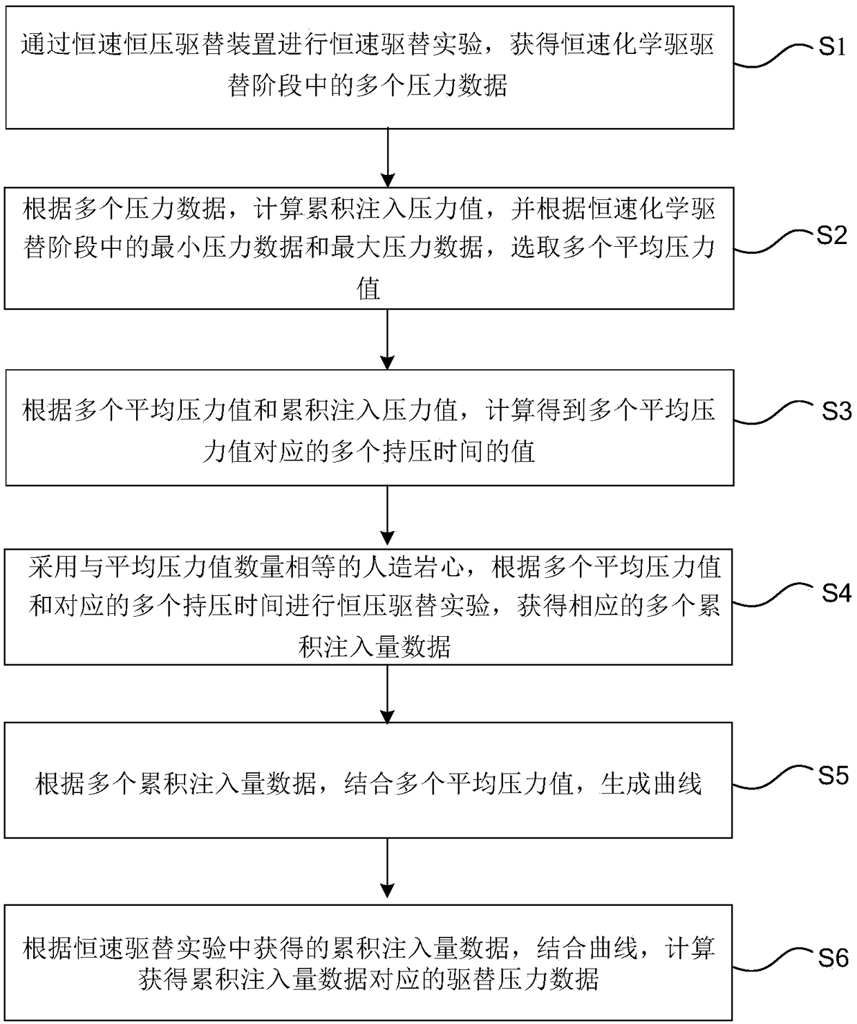
[0067] figure 1 Shows a flow chart of a method for determining the displacement pressure of a constant-rate and constant-pressure chemical flooding experiment provided by the first embodiment of the present invention; The experimental displacement pressure determination method includes:

[0068] Step S1, evacuate the artificial core in the constant-rate and constant-pressure displacement device, saturate it with water and oil, and conduct a constant-rate displacement experiment through the constant-rate and constant-pressure displacement device. The constant-rate displacement experiment includes a constant-rate water displacement stage and constant-rate chemical flooding stage, to obtain multiple pressure data in the constant-rate chemical flooding stage;

[0069] Step S2, calculating the cumulative injection pressure value according to multiple pressure data, and selecting multiple average pressure values ​​according to the minimum pressure data and maximum pressure data in ...

Embodiment 2

[0092] figure 2 A schematic diagram of a displacement pressure determination system 10 of a constant-rate and constant-pressure chemical flooding experiment provided by the second embodiment of the present invention is shown; figure 2 As shown, in the second embodiment of the present invention, a displacement pressure determination system 10 for constant-rate and constant-pressure chemical flooding experiments is provided, including:

[0093] The pressure data acquisition module 101 is used to evacuate the artificial rock core in the constant-rate and constant-pressure displacement device, saturate it with water and oil, and conduct a constant-rate displacement experiment through the constant-rate and constant-pressure displacement device. The constant-rate displacement experiment includes constant Rapid water flooding stage and constant-rate chemical flooding stage, obtain multiple pressure data in the stage of constant-rate chemical flooding;

[0094] The average pressure...

Embodiment 3

[0118] Combining with specific indoor experimental conditions and experimental data, a method and system for determining the displacement pressure of the constant-speed and constant-pressure chemical flooding experiment of the present invention will be described in detail.

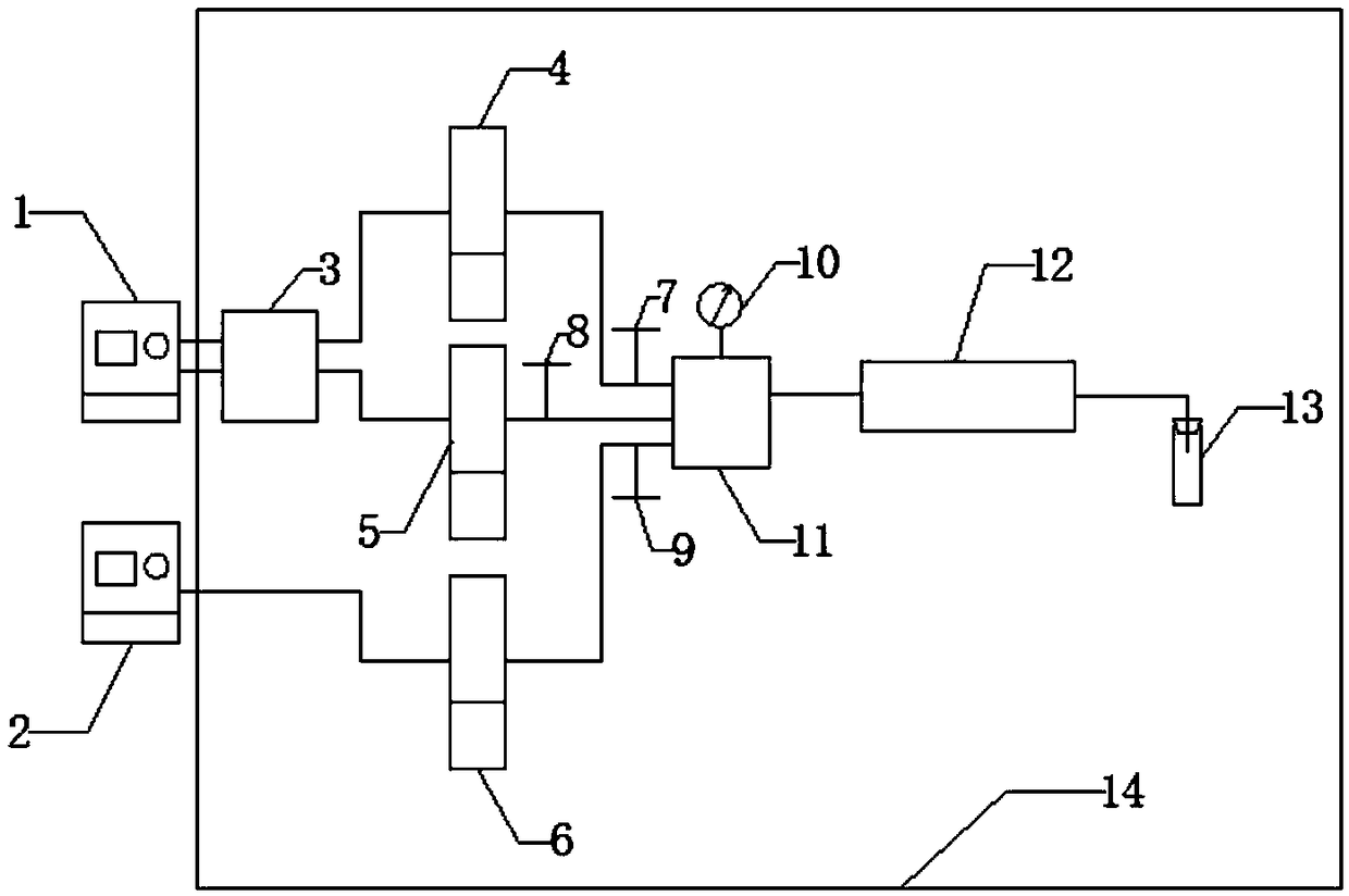
[0119] image 3 It shows a schematic structural diagram of a constant-speed and constant-pressure displacement device provided by the third embodiment of the present invention; as image 3 As shown, according to the constant-speed and constant-pressure displacement device provided in Embodiment 3, it includes:

[0120] Constant speed pump 1, constant pressure pump 2, No. 1 six-way port 3, formation water piston container 4, first chemical agent piston container 5, second chemical agent piston container 6, first valve 7, second valve 8, third valve Valve 9, pressure gauge 10, No. 2 six-way 11, artificial rock core 12, liquid metering device 13 and constant temperature box 14;

[0121] The outlet of the co...


PUM

PropertyMeasurementUnit
porosityaaaaaaaaaa

Abstract

The present invention provides a displacement pressure determination method and system for constant-rate and constant-pressure chemical flooding experiments. The method is: obtain multiple pressure data in the constant-rate chemical flooding stage, calculate the cumulative injection pressure value, and According to the minimum pressure data and maximum pressure data, select multiple average pressure values, and calculate multiple pressure holding times corresponding to multiple average pressure values, and then conduct constant pressure displacement experiments to obtain corresponding multiple cumulative injection data. Combine multiple average pressure values ​​to generate a curve; according to the cumulative injection data obtained in the constant-rate displacement experiment, combine the curves to calculate the displacement pressure data. The method and system for determining the displacement pressure of the constant speed and constant pressure chemical flooding experiment of the present invention can obtain the displacement pressure suitable for the constant pressure displacement experiment through the constant speed and constant pressure experiment. Under the condition of a certain cumulative injection volume, the results of constant velocity and constant pressure experiments can be effectively compared and transformed, and then play a guiding role in mine practice.

Description

technical field [0001] The invention relates to the field of oil and gas field development, in particular to a method and system for determining displacement pressure in constant-speed and constant-pressure chemical flooding oil displacement experiments. Background technique [0002] At present, there are two methods for indoor oil displacement experiments, constant speed experiment and constant pressure experiment. The constant speed experiment means that the displacement speed and constant pressure are always changing during the displacement process. The constant speed experiment can ensure the cumulative injection volume of the displacement agent. The constant pressure experiment is that the pressure is constant during the displacement process, and the displacement speed may change. The constant pressure experiment is close to the field situation, and the displacement pump is used for constant pressure injection. [0003] The constant speed experiment and the constant pre...

Claims


Application Information

Patent Timeline
Patent Type & Authority Patents(China)
IPC IPC(8): G01N33/00
CPCG01N33/00
Inventor 皮彦夫刘丽万雪杨二龙蒋声东李占东
Owner NORTHEAST GASOLINEEUM UNIV
Learn More