A Lifting Mechanism for Realizing Vertical Lifting and Horizontal Elasticity of Furnace Door

A vertical lifting and furnace door technology, which is applied in the direction of furnaces, heat treatment furnaces, furnace components, etc., can solve the problems of equipment costs, use costs that cannot meet energy saving and consumption reduction, cannot meet the requirements of furnace mouth sealing, and furnace doors are not vertically lifted, etc. To achieve the effect of reliable performance, novel design and simple structure

Active Publication Date: 2017-12-26
苏州鼎佳炉窑科技有限公司
View PDF1 Cites 0 Cited by
  • Summary
  • Abstract
  • Description
  • Claims
  • Application Information

AI Technical Summary

Problems solved by technology

The traditional lifting mechanism and pressing are independent and require different driving actuators to operate. The action sequence of the two sets of devices requires an additional detection system and control system to ensure no failure, which has disadvantages in terms of action reliability. ; And in terms of equipment cost and use cost, it cannot meet the requirements of energy saving and consumption reduction
[0003] In addition, in the existing single-drive (motor or hydraulic) furnace door lifting mechanism, the lifting of the furnace door is not vertical lifting, but there is a horizontal displacement during the lifting process, and the pressing and loosening are also achieved by self-weight.
In actual use, it often occurs that the furnace door scratches the furnace end wall parts due to the horizontal displacement during the rising and falling process of the furnace door, and it is impossible to achieve reliable furnace mouth sealing requirements only by self-weight compression. For those with furnace atmosphere requirements There is a risk of leakage for heat treatment furnaces or high-temperature kilns
Therefore, the furnace door lifting mechanism currently used in the industry has relatively large disadvantages, and there is a lot of room for improvement.

Method used


Image

  • A Lifting Mechanism for Realizing Vertical Lifting and Horizontal Elasticity of Furnace Door
  • A Lifting Mechanism for Realizing Vertical Lifting and Horizontal Elasticity of Furnace Door
  • A Lifting Mechanism for Realizing Vertical Lifting and Horizontal Elasticity of Furnace Door

Examples


Embodiment 1

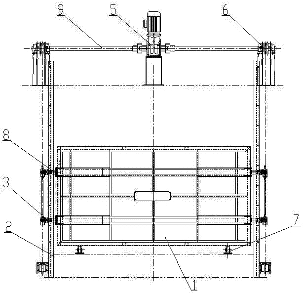
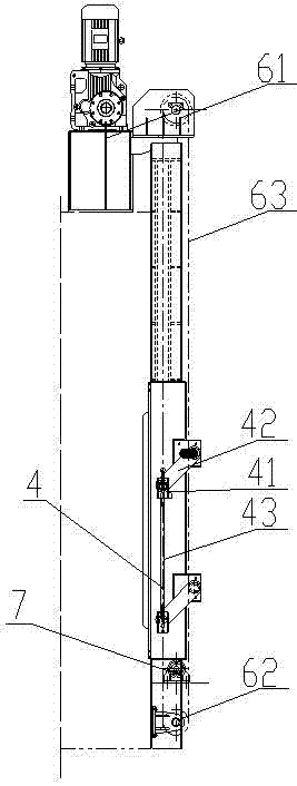
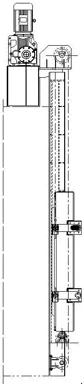
[0016] This embodiment is a lifting mechanism that realizes the vertical lifting and horizontal tightening of the furnace door. The structure is as follows: Figure 1-3 As shown, it includes furnace door 1, guide rail 2, guide wheel 3, parallelogram mechanism 4, drive mechanism 5, chain transmission device 6 and support wheel 7, and the drive mechanism is a double-axis reducer driven by a motor; parallelogram mechanism 4 includes Limit seat 41, connecting plate 42 and a synchronous connecting rod 43, limit seat 41 is provided with the rotating shaft that is connected with connecting plate, the limit seat top is opening structure, is provided with for connecting plate and is horizontal at the limit seat bottom. The two ends of the synchronous connecting rod are each equipped with a limiting seat, which is connected to one end of the connecting plate through the limiting seat, and the other end of the connecting plate is connected to the rotary shaft of the furnace door in rotati...


PUM


Abstract

The invention provides a novel lifting mechanism of a furnace door. Vertical lifting and horizontal pressing and loosening movement of the furnace door can be realized just through single drive elements. The lifting mechanism comprises the furnace door, guide rails, guide wheels, parallelogram mechanisms, drive motors, chain transmission devices and supporting wheels. Two rotation shafts are arranged on two sides of the furnace door, one ends of the parallelogram mechanisms are connected to the rotation shafts of the furnace door, the other ends of the parallelogram mechanisms are connected to the guide wheels, the sections, provided with the guide wheels, of the chain transmission devices are connected into closed-loop chains in a serial mode through the chain transmission devices, and the furnace door can be loosened or pressed just by driving the chain transmission devices through the drive motors and can be vertically lifted along the guide rails when the drive motors continue rotating after loosening or pressing is fully executed. The lifting mechanism is novel in design, simple in structure, high in practicability, low in manufacturing cost and convenient to use, is a simple and reliable vertical lifting and pressing device, can be widely applied to heat treatment furnace kilns of various nonferrous metals and can be applied to transformation of related facilities of existing factories.

Description

technical field [0001] The invention relates to a furnace door lifting mechanism, in particular to a lifting mechanism for realizing the vertical lifting and horizontal tightening of the furnace door, and belongs to the technical field of metal heat treatment equipment. Background technique [0002] At present, especially in the hoisting mechanism of the kiln door of the non-ferrous metal heat treatment furnace, the lifting of the furnace door is mostly driven by a motor, and the pressing and loosening of the furnace door will be more pneumatically pressed and loosened. The traditional lifting mechanism and pressing are independent and require different driving actuators to operate. The action sequence of the two sets of devices requires an additional detection system and control system to ensure no failure, which has disadvantages in terms of action reliability. ; And in terms of equipment cost and use cost, it can not meet the requirements of energy saving and consumption ...

Claims


Application Information

Patent Timeline
Patent Type & Authority Patents(China)
IPC IPC(8): F27D1/18C21D9/00
CPCC21D9/00F27D1/1858
Inventor 尹波平刘建光
Owner 苏州鼎佳炉窑科技有限公司
Why Eureka
Try Eureka