
Bracket for antenna testing equipment and antenna assembly having same

A technology for antenna detection and antenna brackets, which is applied to antenna parts, antenna supports/mounting devices, antennas, etc. It can solve the problems of unfavorable antenna detection equipment for long-term fixed installation, antenna detection equipment not working normally for a long time, and loose brackets. Achieve the effect of long-term fixed installation, real-time and accurate detection and monitoring

Active Publication Date: 2018-12-14
JIANGSU EAST CENTURY NETWORK INFORMATION
View PDF5 Cites 0 Cited by
  • Summary
  • Abstract
  • Description
  • Claims
  • Application Information

AI Technical Summary

Problems solved by technology

However, if this type of top clip-on bracket is used, once the antenna vibrates and tilts or the material is aged and deformed, the bracket may become loose or fall off, which is not conducive to the long-term fixed installation of the antenna testing equipment, so that the antenna testing equipment cannot work normally for a long time. Measured in temporary installations

Method used


Image

  • Bracket for antenna testing equipment and antenna assembly having same
  • Bracket for antenna testing equipment and antenna assembly having same
  • Bracket for antenna testing equipment and antenna assembly having same

Examples


Embodiment Construction

[0036] The embodiments of the present invention are described in detail below. Examples of the embodiments are shown in the accompanying drawings, in which the same or similar reference numerals indicate the same or similar elements or elements with the same or similar functions. The embodiments described below with reference to the drawings are exemplary, and are only used to explain the present invention, but should not be construed as limiting the present invention.

[0037] In the description of the present invention, it should be understood that the terms "center", "longitudinal", "transverse", "length", "width", "thickness", "upper", "lower", "front", " "Back", "Left", "Right", "Vertical", "Horizontal", "Top", "Bottom", "Inner", "Outer", "Clockwise", "Counterclockwise", "Axial" , "Radial", "Circumferential", etc. indicate the orientation or positional relationship based on the orientation or positional relationship shown in the drawings, and are only for the convenience of ...


PUM


Abstract

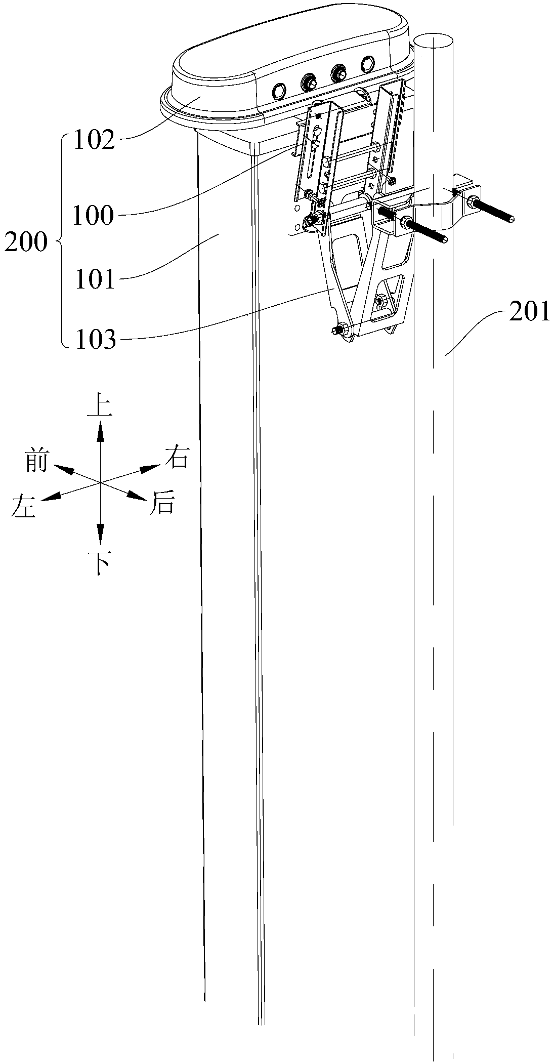
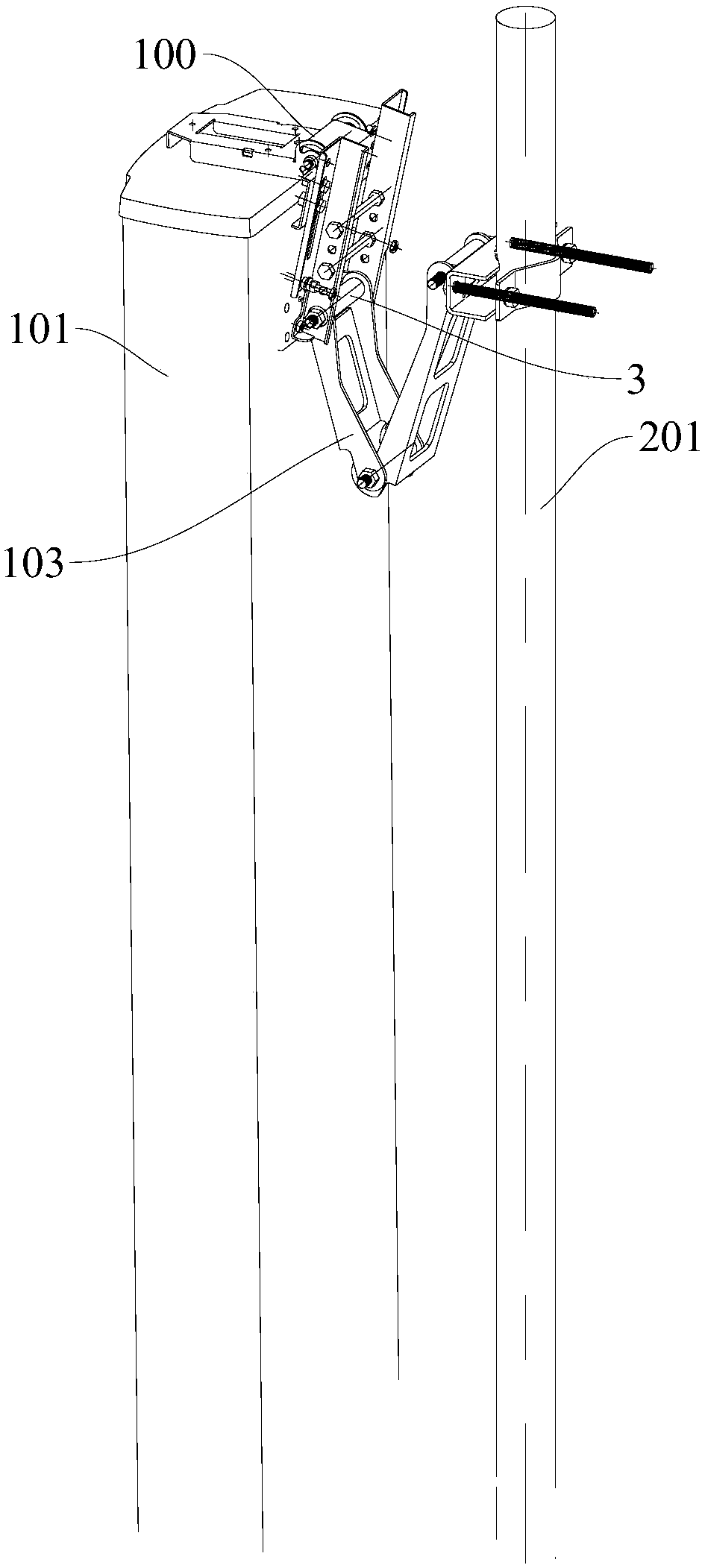
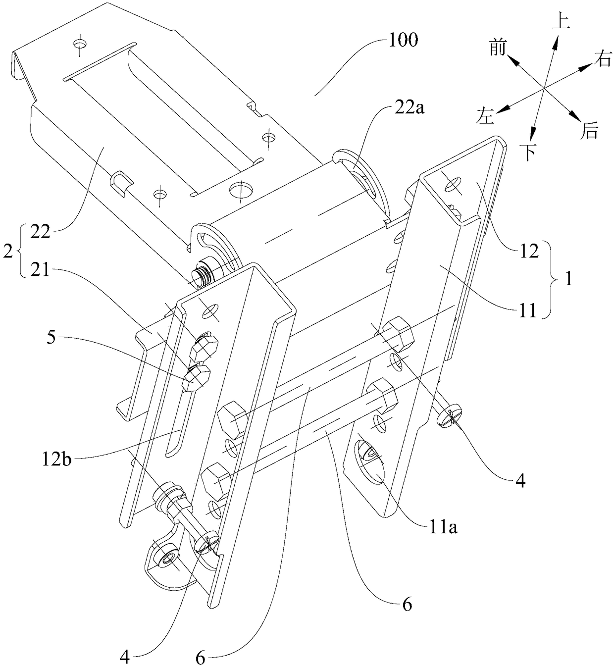
The invention discloses a support used for antenna detection equipment and an antenna assembly with the support. The antenna detection equipment is suitable for being arranged on the top of an antenna, the rear surface of the antenna is connected with a holding rod through the antenna support, and the support comprises a first support and a second support; the first support is suitable for being arranged on the rear side of the antenna, one end of the first support is suitable for being in pivotal connection with one end, connected with the antenna, of the antenna support through a pivot shaft, and two abutting-against parts are arranged on the first support, are located on the two sides of the pivot shaft correspondingly and are suitable for abutting against the rear surface of the antenna; the second support is connected with the first support, the second support is located between the antenna detection equipment and the top of the antenna, and the antenna detection equipment is arranged on the second support. According to the support used for the antenna detection equipment, long-term fixed mounting of the antenna detection equipment is achieved, and the antenna detection equipment can normally work for a long time.

Description

Technical field [0001] The present invention relates to the field of communication technology, and in particular, to a bracket for antenna detection equipment and an antenna assembly having the same. Background technique [0002] The antenna settings in the base station mainly consider engineering parameters such as elevation angle, azimuth angle, antenna height, antenna diversity distance, and isolation distance. These parameters have a decisive influence on the electromagnetic coverage of the base station. Because the base station is exposed to the outdoors for a long time, it is often affected by external factors that cause changes in the antenna's elevation angle, azimuth angle, and position, which in turn affects the base station's expected electromagnetic coverage, resulting in signal blind spots in some locations and serious system Frequency interference. After the above-mentioned problems have occurred, since they cannot provide timely feedback to operators, operators ca...

Claims


Application Information

Patent Timeline
Patent Type & Authority Patents(China)
IPC IPC(8): F16M13/02H01Q1/24
CPCF16M13/02H01Q1/246
Inventor 徐锦锋崔晓辉孟舒
Owner JIANGSU EAST CENTURY NETWORK INFORMATION
Learn More