Linear transmission device

A technology of linear transmission and linear slide, applied in transmission devices, measuring devices, instruments, etc., can solve the problems of poor conduction efficiency, time-consuming and labor-intensive, and shortened life, and achieve the effect of reducing the inaccuracy of measurement signals

Active Publication Date: 2021-07-23
HIWIN TECH
View PDF9 Cites 0 Cited by
  • Summary
  • Abstract
  • Description
  • Claims
  • Application Information

AI Technical Summary

Problems solved by technology

[0003] However, in addition to the above-mentioned transmission assembly requiring an additional cooling device, the transmission assembly is an indirect measurement. Therefore, it is impossible to accurately grasp the change of the internal temperature of the mobile module in measurement, resulting in the signal measured by the thermal sensor 10 It may be inaccurate, produce errors, and even cause long measurement time and poor measurement efficiency.
[0004] Please refer to US Patent No. US4939920A, which provides a mechanical temperature sensing device. When the temperature is higher than the set temperature, the mechanical action cuts off the power supply to protect the safety of the equipment. However, the above-mentioned device cannot In addition to use, the mechanical structure is too complicated, and it is also indirect conduction, so there will be situations such as poor conduction efficiency
[0005] In addition, please refer to the previous Japanese patent JP201725941A, which provides a linear motion guiding device, including: a spring component (refer to the component symbol 232 in the representative figure of JP201725941A) and a sensor for detecting the deformation or vibration of the spring component (Refer to the component symbol 233 in the representative drawing of JP201725941A) to detect the circulation state of the rolling elements with high precision, but this design is not perfect. In order to maintain the accuracy of detection, it must be measured beforehand and carried out afterwards Adjustment is extremely time-consuming and labor-intensive, and this structure cannot measure the internal temperature change in real time, which is prone to problems such as life reduction

Method used


Image

  • Linear transmission device
  • Linear transmission device
  • Linear transmission device

Examples


Embodiment Construction

[0065] The technical solution of the present invention will be clearly and completely described below, obviously, the described embodiments are part of the embodiments of the present invention, rather than all the embodiments. Based on the embodiments of the present invention, all other embodiments obtained by persons of ordinary skill in the art without making creative efforts belong to the protection scope of the present invention.

[0066] Before presenting a detailed description, it is noted that in the following description, similar components are denoted by the same numerals.

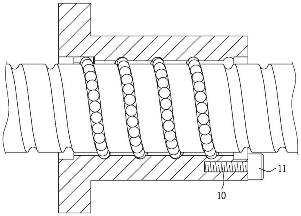
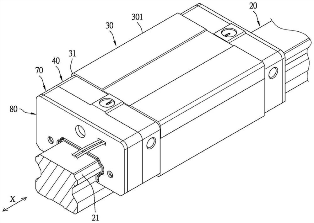
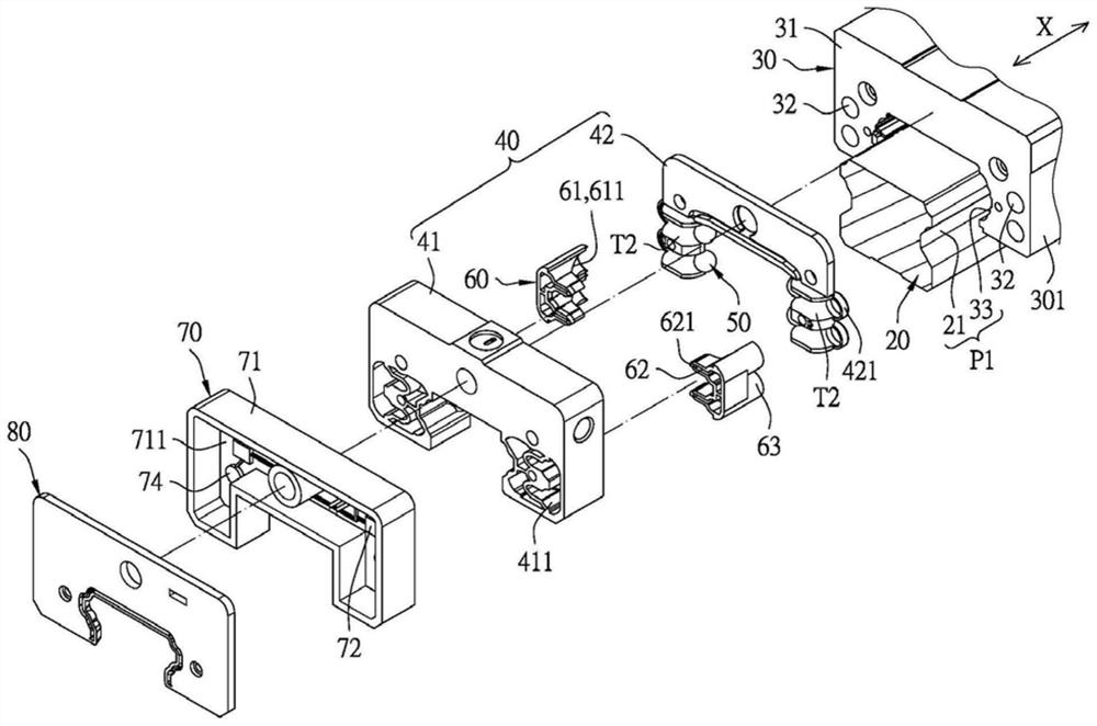
[0067] Such as Figure 2 to Figure 5B As shown, the first embodiment of the present invention provides a linear transmission device, and the linear transmission device is an example of a linear slide rail, but it is not limited to this, or Figure 10 The ball screw shown, wherein the linear transmission device includes:

[0068] The long shaft part 20 extends along the axis X and has a rolling g...


PUM


Abstract

The invention provides a linear transmission device. At least one heat conduction piece is mainly additionally arranged in an infinite circulation path, the at least one heat conduction piece is made of a heat conduction metal material, and therefore when a rolling unit rolls on the infinite circulation path and touches the contact surface of the at least one heat conduction piece, the temperature change in a moving module can be transmitted to a heat energy sensing unit, and then the heat energy sensing unit sends out a sensing signal to a management end to judge whether the linear transmission device is abnormal or not. The linear transmission device is characterized in that the temperature change in the moving module is obtained in a direct measurement manner, the defect of indirect measurement in the prior art is overcome so as to reduce the condition that errors are generated by misalignment of measurement signals, when the linear transmission device is abnormal, the situation can be accurately detected in real time, and the aims of early warning and real-time monitoring can be achieved.

Description

technical field [0001] The present invention relates to a linear transmission device, in particular to a linear transmission device with a heat conducting element. Background technique [0002] Such as figure 1 As shown, one of the diagrams of a transmission assembly with a temperature sensing device in Taiwan Patent (201040413) is shown. The temperature sensing device is mainly composed of a power supply (not shown in the figure), a thermal sensor 10 and a warning device 11 Composition, the thermal sensor 10 absorbs the heat energy of the transmission component, and makes its resistance value drop, so that the warning device 11 is turned on and sends out a signal, which is used to inform the user or start the cooling device to cool the transmission component, so that the transmission component will not be overheated due to its own temperature. High, resulting in poor positioning accuracy, poor lubrication effect or reduced performance. [0003] However, in addition to the...

Claims


Application Information

Patent Timeline
Patent Type & Authority Applications(China)
IPC IPC(8): F16H25/22G01K13/00
CPCF16H25/2204F16H25/22G01K13/00
Inventor 林烨伟陈贤佑
Owner HIWIN TECH
Why Eureka
Try Eureka