
Manufacturing method of reinforcing steel bar section and adjustable reinforcing steel bar section splitting jig frame thereof

A manufacturing method and an adjustable technology, which can be applied in the erection/assembly of bridges, bridges, buildings, etc., can solve the problems that small temporary tire frames cannot be used repeatedly, the thickness of the protective layer of steel bars cannot be unified, and the construction cost is increased. Achieve the effects that are conducive to construction safety and structural quality, improve the construction operating environment, and improve construction efficiency

Active Publication Date: 2017-02-15
ROAD & BRIDGE SOUTH CHINA EINGINEERING CO LTD +1
View PDF7 Cites 10 Cited by
  • Summary
  • Abstract
  • Description
  • Claims
  • Application Information

AI Technical Summary

Problems solved by technology

In the process of steel bar binding, the thickness of the protective layer of steel bars cannot be uniform. It is sometimes large and sometimes small, and the control is difficult. When the number of pier bodies is large and the number of sections is large, the small temporary frame with steel bar spacing and linear control cannot be used repeatedly. It increases the construction cost, and there are certain deficiencies in the on-site binding construction of high pier steel bars

Method used


Image

  • Manufacturing method of reinforcing steel bar section and adjustable reinforcing steel bar section splitting jig frame thereof
  • Manufacturing method of reinforcing steel bar section and adjustable reinforcing steel bar section splitting jig frame thereof
  • Manufacturing method of reinforcing steel bar section and adjustable reinforcing steel bar section splitting jig frame thereof

Examples


Embodiment Construction

[0042] The present invention will be further described below in conjunction with the accompanying drawings and exemplary embodiments. It should be understood that the following specific embodiments are only used to illustrate the present invention and not to limit the scope of the present invention. The same reference numerals in the drawings all refer to the same components.

[0043] Also, detailed descriptions of known arts will be omitted if they are unnecessary to illustrate the features of the present invention. It should be noted that the words "front", "rear", "left", "right", "upper" and "lower" used in the following description refer to the directions in the drawings, and the words "inner" and "outer ” refer to directions towards or away from the geometric center of a particular part, respectively.

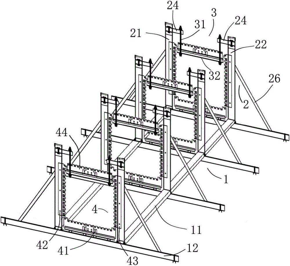
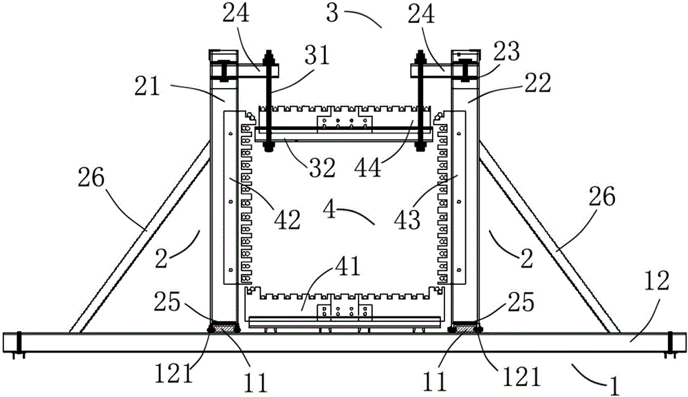
[0044] refer to figure 1 and figure 2 , the present invention provides an adjustable reinforced segment assembled tire frame, which includes a load-bearing platform 1...


PUM


Abstract

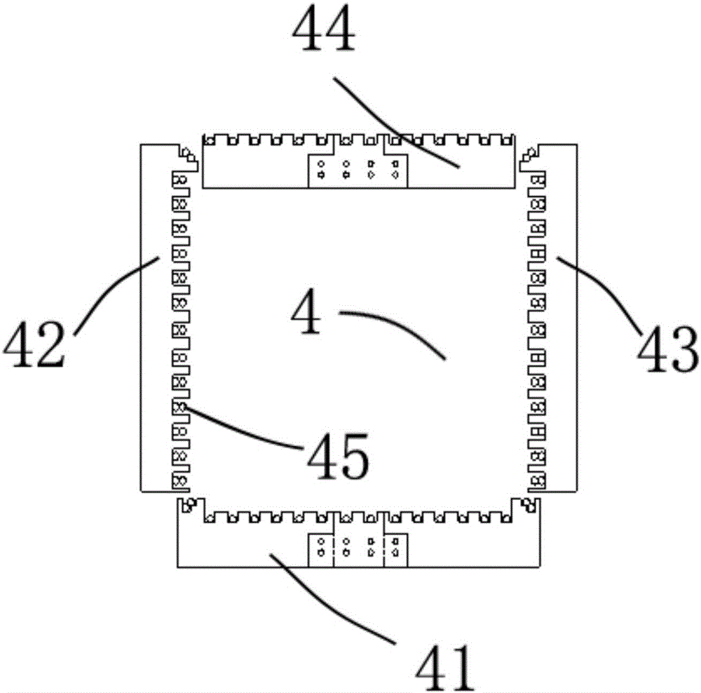
The invention discloses a manufacturing method of a reinforcing steel bar section and an adjustable reinforcing steel bar section splitting jig frame thereof. The adjustable reinforcing steel bar section splitting jig frame comprises a bearing platform, a vertical supporting frame, a suspension frame and a toothed plate set, wherein the bearing platform comprises a pair of longitudinal bearing steels, and a plurality of transverse bearing steels which are orthogonally connected below the longitudinal bearing steels; the vertical supporting frame comprises a plurality of pairs of left supports and right supports; the left supports and the right supports are vertically arranged on the transverse bearing steels; the suspension frame comprises hoisting ribs, and suspension plates which are connected with the left supports and the right supports through the hoisting ribs in a suspension manner; the toothed plate set comprises lower toothed plates which are connected with the corresponding transverse bearing steels, left toothed plates which are connected with the corresponding left supports, right toothed plates connected with the corresponding right supports, and upper toothed plates connected with the corresponding suspension plates. With the adoption of the adjustable reinforcing steel bar section splitting jig frame, a safe and reliable construction environment is provided; in addition, the adjustable reinforcing steel bar section splitting jig frame can be transferred to use and has the characteristics of being fast to bind and manufacture, high in reinforcing steel bar mounting accuracy, and small in workload of aloft work.

Description

[0001] 【Technical field】 [0002] The invention relates to the technical field of bridge engineering, in particular to a method for manufacturing steel bar segments and an adjustable steel bar segment assembled tire frame used. [0003] 【Background technique】 [0004] Due to its small footprint, wide application range and reasonable cost, bridge engineering accounts for an increasing proportion in traffic construction. In the process of bridge pier construction, it is often affected by the external environment, geographical location, construction period, etc. If the conventional on-site steel bar binding construction process is adopted, the cost of manpower and machinery is relatively large. If affected by on-site construction conditions, potential safety hazards will increase. Generally, during the construction process, it is often necessary to increase the input of personnel and machinery to meet the needs of on-site construction, and the difficulty in controlling the quality...

Claims


Application Information

Patent Timeline
Patent Type & Authority Applications(China)
IPC IPC(8): E01D21/00
CPCE01D21/00
Inventor 刁先觉夏江南刘怀刚庞晓欣高世强费永忠夏敏覃鹏飞邱鹏王文王辉唐代新孙棕伟肖向荣檀兴华张铮葛纪平
Owner ROAD & BRIDGE SOUTH CHINA EINGINEERING CO LTD
Learn More