Autotrophic/heterotrophic denitrification-based integrated nitrogen removal apparatus and nitrogen removal method thereof
A technology of heterotrophic denitrification and autotrophic denitrification, which is applied in the field of integrated denitrification devices, can solve the problems of high cost, low efficiency of biological denitrification and denitrification, unstable effluent quality, etc., and achieves cost reduction and good economic benefits. Effect
- Summary
- Abstract
- Description
- Claims
- Application Information
AI Technical Summary
Problems solved by technology
Method used
Image
Examples
Embodiment 1
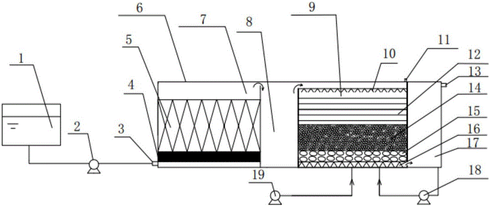
[0024] An integrated denitrification device based on autotrophic / heterotrophic denitrification, including a regulating tank 1, an inlet pump 2, a main reaction device 6, a buffer tank 17, a backwash pump 18, and an aeration pump 19, wherein the main The reaction device 6 includes an autotrophic denitrification zone 7, a buffer cavity 8 and a heterotrophic denitrification zone 9, the buffer cavity 8 is located between the autotrophic denitrification zone 7 and the heterotrophic denitrification zone 9, The autotrophic denitrification zone 7 and the heterotrophic denitrification zone 9 are functionally independent from each other through the buffer cavity 8, and the regulating pool 1 is connected to the autotrophic denitrification zone 7 through the inlet pump 2 The liquid inlet 3 is connected; the autotrophic denitrification zone 7 includes a micro-electrolysis filler layer 4 and a sulfur / limestone filler layer 5, and the micro-electrolysis filler layer 4 is located at the bottom...
Embodiment 2
[0034] An integrated denitrification device based on autotrophic / heterotrophic denitrification, including a regulating tank 1, an inlet pump 2, a main reaction device 6, a buffer tank 17, a backwash pump 18, and an aeration pump 19, wherein the main The reaction device 6 includes an autotrophic denitrification zone 7, a buffer cavity 8 and a heterotrophic denitrification zone 9, the buffer cavity 8 is located between the autotrophic denitrification zone 7 and the heterotrophic denitrification zone 9, The autotrophic denitrification zone 7 and the heterotrophic denitrification zone 9 are functionally independent from each other through the buffer cavity 8, and the regulating pool 1 is connected to the autotrophic denitrification zone 7 through the inlet pump 2 The liquid inlet 3 is connected; the autotrophic denitrification zone 7 includes a micro-electrolysis filler layer 4 and a sulfur / limestone filler layer 5, and the micro-electrolysis filler layer 4 is located at the bottom...
Embodiment 3
[0044] An integrated denitrification device based on autotrophic / heterotrophic denitrification, including a regulating tank 1, an inlet pump 2, a main reaction device 6, a buffer tank 17, a backwash pump 18, and an aeration pump 19, wherein the main The reaction device 6 includes an autotrophic denitrification zone 7, a buffer cavity 8 and a heterotrophic denitrification zone 9, the buffer cavity 8 is located between the autotrophic denitrification zone 7 and the heterotrophic denitrification zone 9, The autotrophic denitrification zone 7 and the heterotrophic denitrification zone 9 are functionally independent from each other through the buffer cavity 8, and the regulating pool 1 is connected to the autotrophic denitrification zone 7 through the inlet pump 2 The liquid inlet 3 is connected; the autotrophic denitrification zone 7 includes a micro-electrolysis filler layer 4 and a sulfur / limestone filler layer 5, and the micro-electrolysis filler layer 4 is located at the bottom...
PUM
| Property | Measurement | Unit |
|---|---|---|
| particle diameter | aaaaa | aaaaa |
| particle diameter | aaaaa | aaaaa |
| particle diameter | aaaaa | aaaaa |
Abstract
Description
Claims
Application Information
 - Generate Ideas
- Intellectual Property
- Life Sciences
- Materials
- Tech Scout
- Unparalleled Data Quality
- Higher Quality Content
- 60% Fewer Hallucinations
Browse by: Latest US Patents, China's latest patents, Technical Efficacy Thesaurus, Application Domain, Technology Topic, Popular Technical Reports.
© 2025 PatSnap. All rights reserved.Legal|Privacy policy|Modern Slavery Act Transparency Statement|Sitemap|About US| Contact US: help@patsnap.com

