Straightening structure for groove-shaped rail

A grooved rail and straightening technology, which is applied in the field of profile rolling, can solve problems such as waist bending deformation, asymmetry, and cracking at the bottom of the rail groove, so as to optimize the stress state, prevent waist deformation, and ensure balance.

Active Publication Date: 2017-02-15
PANGANG GRP PANZHIHUA STEEL & VANADIUM
View PDF7 Cites 4 Cited by
  • Summary
  • Abstract
  • Description
  • Claims
  • Application Information

AI Technical Summary

Problems solved by technology

[0002] At present, the correction method adopted for the asymmetry between the rail head and the rail lip of the grooved rail, especially for the technical problem that there is a gap of about 6 mm between the highest point of the rail head and the rail lip, has the following defects. When the upper straightening roller adopts the rail lip and the rail head to bear the force in pass design, there will be two problems: 1. The elastic deformation of the rail lip is greater than that of the rail head, causing the deformation to be biased to the rail head side, causing the waist to bend and deform
2. When the force on the rail lip is too large, stress concentration occurs at the bottom of the rail groove, causing the bottom of the rail groove to crack
Therefore, the traditional straightening structure is difficult to meet the actual production needs

Method used


Image

  • Straightening structure for groove-shaped rail
  • Straightening structure for groove-shaped rail
  • Straightening structure for groove-shaped rail

Examples


Embodiment Construction

[0017] The present invention will be further described below in conjunction with the accompanying drawings.

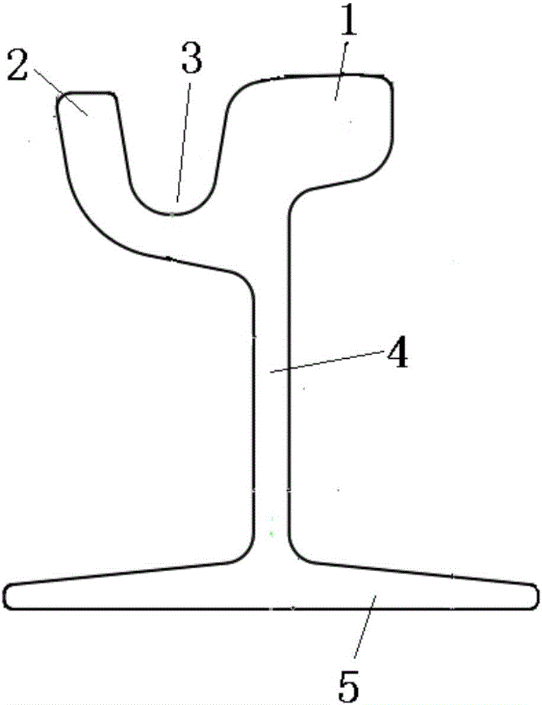
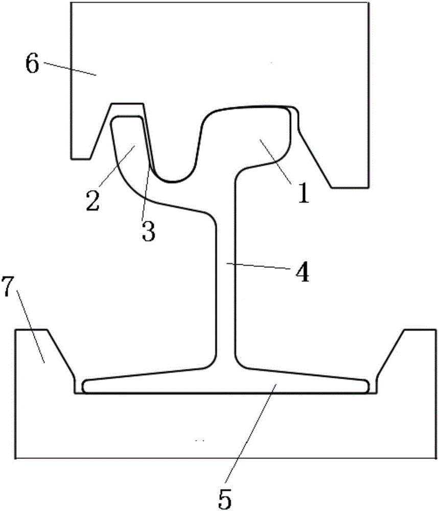
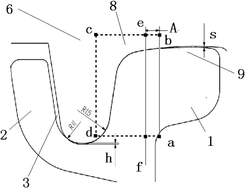
[0018] Such as figure 1 , figure 2 , image 3 The straightening structure of the grooved rail shown includes the grooved rail to be straightened. The top of the grooved rail is composed of a rail head 1, a rail groove 3 and a rail lip 2, the middle part is composed of a rail waist 4, and the bottom is composed of a rail bottom 5 It also includes a straightening roller composed of a straightening upper roller 6 and a straightening lower roller 7, the rail bottom 5 of the grooved rail is arranged on the straightening lower roller 7, and the straightening upper roller 6 is arranged on the rail head 1 and the rail groove 3 Above, the straightening upper roller 6 is embedded in the rail groove 3 and is attached to the inner wall of the rail groove 3 through the left arc (R11) and the right arc (R15) of the straightening upper roller 6 respectively, and the straightening ...


PUM

PropertyMeasurementUnit
radiusaaaaaaaaaa

Abstract

The invention relates to the field of sectional material rolling, in particular to a straightening structure for a groove-shaped rail. According to the technical purpose to be achieved, the straightening structure for the groove-shaped rail is provided, a hole pattern straightening structure is designed for the phenomenon that the waist part of the groove-shaped rail is likely to be subjected to bending deformation in the straightening process, the stressed state of bending deformation during straightening is optimized, and waist part deformation on the section cannot be generated while the groove-shaped rail is bent. The straightening structure comprises the groove-shaped rail to be straightened. The top of the groove-shaped rail is composed of a rail head, a rail groove and a rail lip. The middle portion of the groove-shaped rail is composed of a rail waist. The bottom of the groove-shaped rail is composed of a rail bottom. The straightening structure comprises a straightening roller composed of an upper straightening roller body and a lower straightening roller body. The rail bottom of the groove-shaped rail is arranged on the lower straightening roller body. The upper straightening roller body is arranged on the rail head and the rail groove. The upper straightening roller body is embedded in the rail groove and is attached to the inner wall of the rail groove through a left side arc and a right side arc of the upper straightening roller body. An interference gap is arranged between the bottommost end, embedded in the rail groove, of the upper straightening roller body and the bottommost end of the adjacent rail groove. The straightening structure is particularly suitable for technology occasions where the groove-shaped rail is accurately corrected.

Description

technical field [0001] The invention relates to the field of profile rolling, in particular to a grooved rail straightening structure. Background technique [0002] At present, the correction method adopted for the asymmetry between the rail head and the rail lip of the grooved rail, especially for the technical problem that there is a gap of about 6 mm between the highest point of the rail head and the rail lip, has the following defects. When the upper straightening roller adopts the rail lip and the rail head to bear the force in pass design, there will be two problems: 1. The elastic deformation of the rail lip is greater than that of the rail head, causing the deformation to be biased to the rail head side, causing the waist to bend and deform . 2. When the force on the rail lip is too large, stress concentration will occur at the bottom of the rail groove, causing the bottom of the rail groove to crack. Therefore, the traditional straightening structure is difficult ...

Claims


Application Information

Patent Timeline
Patent Type & Authority Applications(China)
IPC IPC(8): B21D3/02
CPCB21D3/02
Inventor 陶功明朱华林许健
Owner PANGANG GRP PANZHIHUA STEEL & VANADIUM
Why Eureka
Try Eureka