Angled connector

A connector and bending technology, applied in the direction of connection, parts of the connection device, coupling device, etc., can solve the problems of inconvenient assembly, limited assembly space, etc., and achieve the effect of solving inconvenient assembly and satisfying sealing performance

Active Publication Date: 2018-11-13
CHINA AVIATION OPTICAL-ELECTRICAL TECH CO LTD
View PDF9 Cites 0 Cited by
  • Summary
  • Abstract
  • Description
  • Claims
  • Application Information

AI Technical Summary

Problems solved by technology

Since the opening at the rear end of the plug-in housing 11 is located on the rear end face of the plug-in housing, the size of the opening is limited by the size of the plug-in housing, so that the assembled insulator and the wires and contacts that are crimped together The assembly space is limited, resulting in inconvenient assembly

Method used


Image

  • Angled connector
  • Angled connector
  • Angled connector

Examples


Embodiment Construction

[0012] Embodiments of the present invention will be further described below in conjunction with the accompanying drawings.

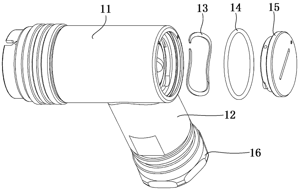
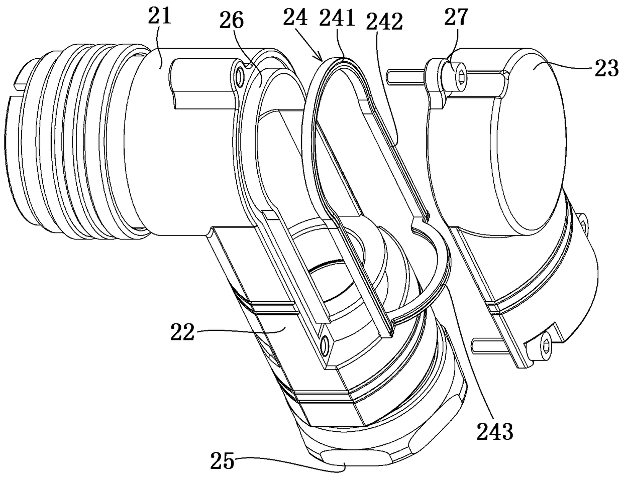
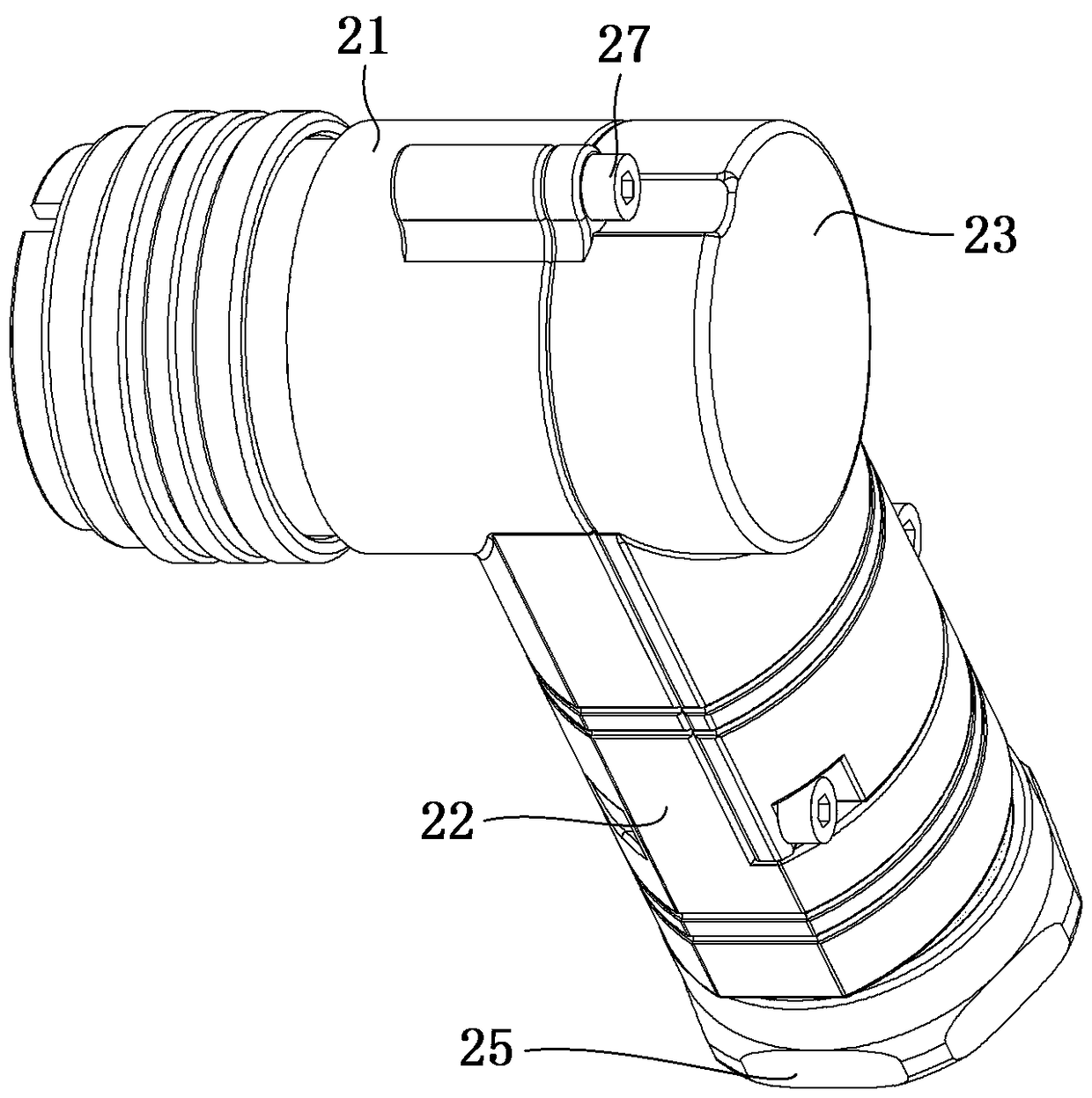
[0013] The specific embodiment of the bent connector of the present invention, such as figure 2 and image 3 As shown, the bent connector includes a connector housing made of metal. The connector housing includes a plug-in housing 21 with a plug-in terminal at the front end and a terminal housing 22 for wiring. The terminal housing 22 is at a right angle. It is connected with the plug-in housing 21 , and the inner cavities of the plug-in housing 21 and the terminal housing 22 communicate with each other after they are connected. The rear end of the connector housing is provided with an opening, and the opening includes an upper opening on the end face of the plug-in housing and a lower opening extending along the axial direction of the terminal housing, and a retaining edge 26 is provided at the opening. The opening is provided with a tail cap 23 whos...


PUM


Abstract

The invention relates to an angle connector. The back end of a connector shell of the angle connector is provided with an opening. A tail cap shaped to match the opening is mounted on the opening. The opening includes a plugging end shell part and a wiring end shell part. The tail cap includes an upper part used for sealing the plugging end shell part of the shell and a lower part used for sealing the wiring end shell part of the opening. As the opening includes the wiring end shell part, the opening gets larger, an insulator as well as a wire and a contact element pressure-welded together are easy to assemble, and the problem that assembly is inconvenient during wiring of an angle connector is solved. Moreover, a sealing gasket is arranged between the opening and the abut-joint side of the tail cap, so that the sealing performance of the angle connector satisfies the needs.

Description

technical field [0001] The invention relates to an angled connector. Background technique [0002] The structure of an existing bent connector is as follows: figure 1 As shown, the connector housing includes a plug-in terminal housing 11 with a plug-in terminal at the front end and a terminal housing 12 for connecting a fixed cable. The rear end surface of the terminal housing 11 is provided with an opening, the front end of the terminal housing 12 is connected to the outer circumference of the plug terminal housing 11, the rear end is provided with a nut 16, and the terminal housing 12 is provided with a sealing wire. The sealing structure of the cable, specifically the sealing ring. When this type of connector is assembled, the insulator is first loaded into the opening, and then the contact piece is crimped on the wires of the cable and inserted into the plug-in housing 11 through the opening at the rear end of the housing 11 and fixed. After the contact piece is fixed...

Claims


Application Information

Patent Timeline
Patent Type & Authority Patents(China)
IPC IPC(8): H01R13/502H01R13/52
CPCH01R13/502H01R13/5202H01R13/5213
Inventor 顾文武
Owner CHINA AVIATION OPTICAL-ELECTRICAL TECH CO LTD
Why Eureka
Try Eureka