Spiral spring damper with early rigidity capable of being adjusted

A helical spring and damper technology, which is applied in the direction of spring/shock absorber, spring/shock absorber functional characteristics, spring, etc., can solve the problems of waste of resources, reduce the cost of shock absorption, and inappropriateness, so as to shorten the length and reduce the The Effect of Seismic Isolation Costs

Active Publication Date: 2017-02-08
WANDA CASTERS & HARDWARE MFG CO LTD
View PDF8 Cites 2 Cited by
  • Summary
  • Abstract
  • Description
  • Claims
  • Application Information

AI Technical Summary

Problems solved by technology

However, this utility model patent obviously has the following disadvantages: 1. Two coil springs are required, and the length of the entire damper is relatively long, which is not suitable for installation in a space with a small distance; 2. It is difficult or even impossible to ensure the two springs in the process Only the stiffness of the spring (including tensile stiffness and compression stiffness) is equal, so the shock absorption effect is different in different wind directions; 3. The early stiffness of the damper cannot be changed to achieve the preset wind resistance level and reduce the cost of shock absorption; 4. A helical spring works in two states of tension and compression at the same time. The metal material and production process of the existing spring are difficult to meet the requirements. The two working states of tension and compression can only be realized by reducing the elastic deformation range of the helical spring. , which obviously wastes resources
It can be seen that although the stiffness of the spring in the patent application scheme can be changed, the effective working length of the spring is not only significantly shortened, but also can only be compressed for energy consumption and vibration reduction, and cannot be stretched for energy consumption and vibration reduction.
In addition, the stiffness of the spring is changed by changing the effective working length of the spring. The adjustment range is limited by the material and shape of the spring itself.

Method used


Image

  • Spiral spring damper with early rigidity capable of being adjusted
  • Spiral spring damper with early rigidity capable of being adjusted
  • Spiral spring damper with early rigidity capable of being adjusted

Examples


example 1

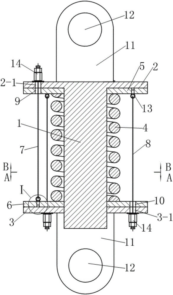
[0035] see figure 1 and 5 , the helical spring damper with adjustable early stiffness in this example is a kind of damper that can be used for seismic reinforcement of building structures. shaped helical compression spring 4, wherein the upper end plate 2 is provided with a guide rod 1, and the guide rod 4 passes through the lower end plate 3 downwards along the center hole of the cylindrical helical compression spring 4; the lower end plate 3 and the guide rod 1 Move and cooperate.

[0036] see figure 1 , 4 and Figure 5 , the upper surface of the upper end plate 2 and the lower surface of the lower end plate 3 are respectively provided with two connecting ear plates 11 with hinged holes 12 . And the distance between the hinged hole 12 on the lower end plate 3 and the lower end plate 3 is greater than the length of the end of the guide rod 1 passing through the lower surface of the lower end plate 3 . A flexible space for the expansion and contraction of the end of th...

example 2

[0050] see Figures 13 to 17 , this example has the following differences from example 1:

[0051] 1. Both the first group of preloaded steel wire ropes 8 and the second group of preloaded steel wire ropes 7 are composed of three steel wire ropes. The number of the steel cable self-locking tensioning anchors 14 is six.

[0052] 2. In order to prevent dust and other debris from falling on the cylindrical helical compression spring 4 and affect the normal operation of the damper, a layer of rubber protective sleeve 15 is wrapped on the outside of the back pressure device. The two ends of the protective sleeve 15 are respectively connected to the first The outer peripheral surfaces of the floating platen 6 and the second floating platen 5 are glued together. The length of the sheath 15 is greater than the distance between the upper surface of the upper end plate 2 and the lower surface of the lower end plate 3, so as not to affect the work of the damper.

[0053] The implement...

example 3

[0055] see Figure 18-22 , the helical spring damper with adjustable early stiffness in this example is a vibration isolation device (also known as isolation support) that can be used for vertical isolation of buildings. Compared with Example 2, this example mainly has the following differences:

[0056] 1. As a vibration isolation support, in order to facilitate installation, in this example, the connecting ear plate on the upper end plate 2 is omitted, and the edge of the upper end plate 2 is first extended axially upward and then radially outward, and at the edge Connecting bolt holes 16 are evenly arranged at each position; wherein, the length extending axially upwards needs to be greater than the height of the self-locking tensioning anchor 14 of the steel cable.

[0057]2. The connecting lugs provided on the outside of the lower end plate 3 are omitted, and the lower end plate 3 is extended axially downward from the edge and then radially outward to form the base of the ...


PUM


Abstract

The invention discloses a spiral spring damper with early rigidity capable of being adjusted. The spiral spring damper is characterized in that a back pressure is arranged between two end plates of the damper, the back pressure device comprises two sets of prepressing steel cables with the number being three or more in each set and two floating pressing plates, wherein each floating pressing plate is arranged on a guide rod between one end plate and a cylindrical spiral compressed spring in a sleeving mode, the two sets of prepressing steel cables are symmetrically distributed on the periphery of the cylindrical spiral compressed spring in a linear state about the axes of the guide rods correspondingly, one ends of each set of prepressing steel cables are fixed to one floating pressing plate, the other ends of each set of prepressing steel cables penetrate through the other floating pressing plate to be anchored to the corresponding end plate adjacent to the floating pressing plate through a steel cable self-locking tensioning anchor gear, the two sets of prepressing steel cables are tensioned, and the cylindrical spiral compressed spring is always clamped between the two floating pressing plates.

Description

technical field [0001] The present invention relates to shock absorbing devices, and more particularly to dampers employing helical compression springs. Background technique [0002] A damper is a shock-absorbing device that consumes motion energy by providing motion resistance. The use of dampers for energy dissipation and shock absorption is a traditional technology widely used in industries such as aerospace, aviation, military industry, guns, and automobiles. Since the 1970s, people have gradually applied the technology of using dampers to consume energy and reduce shocks to structural engineering such as buildings, bridges, and railways. The coil spring damper is widely used in the anti-seismic structures of various buildings because of its high impact resistance, low cost and good shock absorption effect. [0003] People pursue a comprehensive anti-seismic performance combining "resistance" and "loss" for the design of buildings, especially the anti-seismic structure...

Claims


Application Information

Patent Timeline
Patent Type & Authority Applications(China)
IPC IPC(8): F16F7/00F16F1/12E04B1/98E04H9/02
CPCE04B1/98E04H9/021F16F1/121F16F7/00F16F2228/066F16F2228/08F16F2234/02F16F2238/026
Inventor 沈珊胡济福胡济全
Owner WANDA CASTERS & HARDWARE MFG CO LTD
Why Eureka
Try Eureka