


Quick Research
Generate reliable direction feasibility study reports for your R&D in just a few steps.

Technical Q&A
Discover and master advanced knowledge NOW. Basics, ideas, possibilities, all at once.

Find Solutions
As an expert in R&D theories, this can generate solutions to your technical problems instantly.

Evaluate Feasibility
Analyze your overall solution with one click, know your potential R&D risks in advance.

Monitor Landscape
Get weekly tech updates, stay abreast of the latest tech innovations and key insights.
Composite spring damper with early rigidity capable of being preset
A composite spring and damper technology, applied in the direction of spring/shock absorber, spring/shock absorber functional characteristics, spring, etc. The effect of isolation cost
- Summary
- Abstract
- Description
- Claims
- Application Information
AI Technical Summary
Problems solved by technology
Method used
Image

Examples
example 1
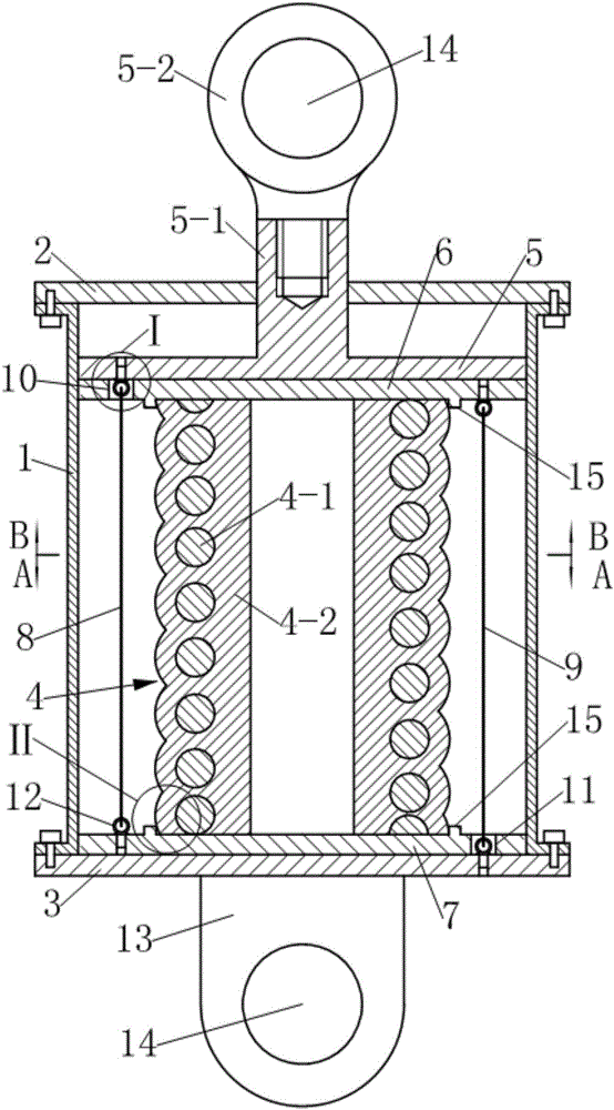
[0039] see figure 1 , the composite spring damper with preset stiffness in the early stage in this example is an energy dissipation device that can be used for seismic reinforcement of building structures. It includes a guide sleeve 1, a first end cover 2 and a second Two end caps 3, wherein the first end cap 2 and the second end cap 3 are respectively fixedly connected to the two ends of the guide sleeve by screws. A composite spring 4 is arranged axially in the guide sleeve 1, and a driving member protrudes from the center of the first end cover 2 into the guide sleeve 1 and presses on the composite spring 4; wherein, the drive The component is composed of a dynamic pressure plate 5 located at the upper end of the composite spring 4 and movingly matched with the guide sleeve 1, and a driving rod 5-1 extending upward from the upper surface of the dynamic pressure plate 5 out of the guide sleeve 1. The driving rod 5-1 is located on the guide sleeve 1. The outer end is provid...
example 2
[0049] This example has the following differences from Example 1:
[0050] see Figure 8-10 , the first group of preloaded steel cables 8 and the second group of preloaded steel cables 9 are composed of three steel cables.
[0051] see Figures 8 to 13 , the upper head of the first group of preloaded steel cables 8 and the lower head of the second group of preloaded steel cables 9 are respectively fixed on the dynamic pressure plate 5 and the second set of steel cables by using cable self-locking anchors 16 instead of the eyebolts in Example 1. On the two end caps 3.
[0052] see Figures 14 to 16 , and combined with Figure 7 , the cable self-locking anchor 16 is composed of a mounting hole provided on the mounting plate 16-1, a jaw 16-2 and a locking bolt 16-4, wherein the mounting plate 16-1 is a movable Pressing plate 5 or second end cap 3 . The axis of the mounting hole is collinear with the straight line where the corresponding pre-compressed steel cable is located...
example 3
[0056] see Figures 17-21 , the composite spring damper with preset stiffness in the early stage in this example is a kind of vibration isolation device (also called seismic isolation support) that can be used for vertical seismic isolation of buildings. Compared with Example 2, this example mainly has the following differences :
[0057] 1. As a shock-absorbing support, in order to facilitate installation, in this example, the connecting lug plate provided on the second end cover 3 in Example 2 is omitted, and the second end cover 3 is extended axially downward from the edge and then to the It extends radially outward, and is evenly provided with connecting bolt holes 18 at the edge. The second end cover 3 is used as the base of the shock-isolation support, and the length of the downward axial extension needs to be greater than the self-locking anchor 16 of the steel cable. The length of the part exposed on the outside of the second end cover 3 . The driving rod 5-1 of the ...
PUM
 Abstract
Description
Claims
Application Information
 - R&D Engineer
- R&D Manager
- IP Professional
- Industry Leading Data Capabilities
- Powerful AI technology
- Patent DNA Extraction
Browse by: Latest US Patents, China's latest patents, Technical Efficacy Thesaurus, Application Domain, Technology Topic, Popular Technical Reports.
© 2024 PatSnap. All rights reserved.Legal|Privacy policy|Modern Slavery Act Transparency Statement|Sitemap|About US| Contact US: help@patsnap.com