Magnetic coupling drive seal type draught fan

A sealed, magnetic coupling technology, applied in the direction of permanent magnet clutches/brakes, machines/engines, liquid fuel engines, etc., can solve problems affecting the refrigeration efficiency of circulating nitrogen gas, so as to avoid refrigeration efficiency, ensure sealing, and improve replacement The effect of thermal efficiency

Inactive Publication Date: 2017-02-08
PHST CORP
View PDF5 Cites 4 Cited by
  • Summary
  • Abstract
  • Description
  • Claims
  • Application Information

AI Technical Summary

Problems solved by technology

In a narrow airtight space, the motor and impeller of the fan are placed in it. In addition to the space limitation, the heat dissipation of the motor itself will also affect the cooling efficiency of the circulating nitrogen.

Method used


Image

  • Magnetic coupling drive seal type draught fan
  • Magnetic coupling drive seal type draught fan
  • Magnetic coupling drive seal type draught fan

Examples


Embodiment Construction

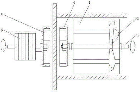
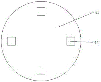
[0014] like Figure 1 to Figure 3 As shown, a magnetically coupled drive sealed fan includes a fan main body 1, the fan main body 1 is sealed in a non-magnetic closed space, the fan main body 1 includes a fan drive shaft 2, a fan impeller 3 and an inner Magnetic device 4, the inner magnetic device 4 is installed on the shaft end of the fan drive shaft 2, the fan impeller 3 and the inner magnetic device 4 are coaxially connected in the middle of the shaft of the fan drive shaft 2, so A driving motor 5 is arranged on the outside of the fan main body 1, and the driving motor 5 is connected to an external magnetic device 6, the external magnetic device 6 is opposite to the internal magnetic device 4, and the external magnetic device 6 is connected to the internal magnetic device 4. Magnetic means 4 are coupled.

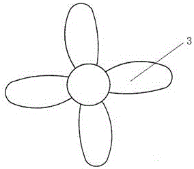
[0015] Preferably, the fan impeller 3 is a helical axial flow impeller, which is designed according to the working environment and efficiency requirements of the magneti...


PUM


Abstract

The invention provides a magnetic coupling drive seal type draught fan. A draught fan body is sealed in a sealed space free of magnetic conduction, and comprises a draught fan drive shaft, a draught fan impeller and an inner magnetic device; the inner magnetic device is mounted at the shaft end of the draught fan drive shaft, the draught fan impeller and the inner magnetic device are coaxially connected to the middle of the draught fan drive shaft, a drive motor is arranged outside the draught fan body and is connected with an outer magnetic device, and the outer magnetic device and the inner magnetic device are opposite and are coupled. Power non-contact transmission is achieved, the draught fan body can be completely sealed in the seal space, use space of the seal space is saved, system seal is ensured, the phenomenon that the heat dissipation of the motor affects the refrigeration efficiency of circular nitrogen is avoided, and the system heat exchange efficiency is improved.

Description

technical field [0001] The invention relates to a fan, in particular to a magnetic coupling driven sealed fan. Background technique [0002] In the confined space of industrial equipment, since some components and parts (such as filaments, etc.) In the space to be cooled), fans are used to circulate and refrigerate the nitrogen, and the nitrogen is circulated to exchange heat with the cooling medium to remove heat, so as to achieve the purpose of cooling parts and components in the confined space. In a narrow confined space, the motor and impeller of the fan are placed in it. In addition to the space restriction, the heat dissipation of the motor itself will also affect the cooling efficiency of the circulating nitrogen. Contents of the invention [0003] In order to solve the deficiencies in the prior art, the present invention provides a magnetic coupling driven sealed fan, the driving motor is externally mounted, and the impeller is driven by magnetic coupling, which s...

Claims


Application Information

Patent Timeline
Patent Type & Authority Applications(China)
IPC IPC(8): F04D25/06F04D29/32H02K49/10
CPCF04D25/06F04D29/325H02K49/108
Inventor 张翔
Owner PHST CORP
Why Eureka
Try Eureka