
Hydraulic torque wrench

A torque wrench and hydraulic technology, applied in the field of torque wrench, can solve the problem of low torque output accuracy and achieve high torque output accuracy

Inactive Publication Date: 2017-02-08
AVIC SHAANXI DONGFANG AVIATION INSTR
View PDF8 Cites 0 Cited by
  • Summary
  • Abstract
  • Description
  • Claims
  • Application Information

AI Technical Summary

Problems solved by technology

[0003] In view of this, the task of the present invention is to propose a hydraulic torque wrench, to overcome the shortcomings of the existing hydraulic torque wrench torque output accuracy is not high

Method used


Image

  • Hydraulic torque wrench
  • Hydraulic torque wrench
  • Hydraulic torque wrench

Examples


Embodiment Construction

[0018] The present invention will be further described below in conjunction with the embodiments and accompanying drawings.

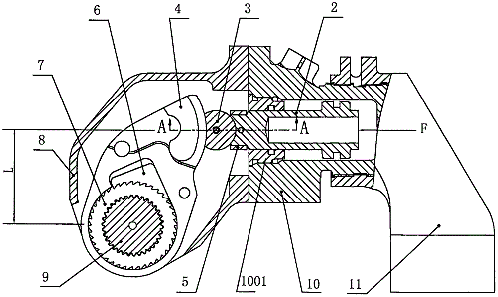
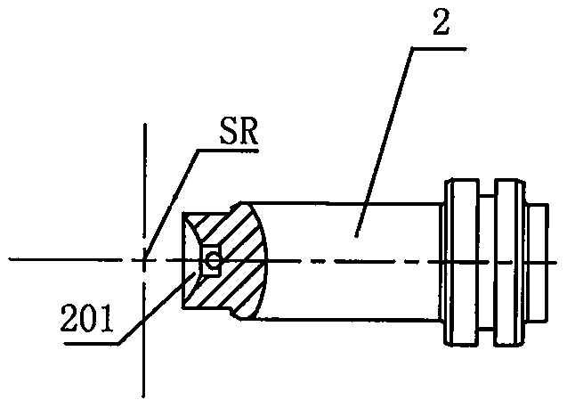
[0019] Such as Figure 2 to Figure 8 As shown, the present invention includes a ratchet mechanism and a loading mechanism. The loading mechanism includes a hydraulic cylinder 10 installed on a reaction arm 11 and a piston 2 of the hydraulic cylinder 10. The ratchet mechanism includes a drive plate 4, and the upper end of the drive plate 4 is a force end. , the lower end is the power end that engages with the ratchet 7 through the ratchet 6 and drives the ratchet 7 to rotate. The feature that is different from the prior art is: the end face of the head of the piston 2 protruding from the cylinder end cover 1001 is a spherical concave surface 201, the end face of the force-bearing end of the driving plate 4 is a longitudinal arc-shaped convex surface 401, and the piston 2 A spherical segmented rotating seat 3 is installed between the protruding end and t...


PUM


Abstract

The invention discloses a hydraulic torque wrench which comprises a ratchet mechanism and a loading mechanism. The loading mechanism comprises a hydraulic cylinder piston. The ratchet mechanism comprises a driving plate. The end face of the head of the extending end of the piston is a spherical segment concave face. The end face of the stressed end of the driving plate is a longitudinal circular arc convex face. A spherical segment rotating base is installed between the extending end of the piston and the stressed end of the driving plate. The bottom face of the rotating base is an inner sunken face. The spherical radius of the rotating base is equal to the radius of the spherical segment concave face. The radius of the inner sunken face is equal to the radius of the circular arc convex face. The spherical face of the rotating base is in sliding fit with the spherical segment concave face of a piston rod. The inner sunken face is in sliding fit with the circular arc convex face of the driving plate. A connecting piece for keeping linkage among the piston, the rotating base and the driving plate is installed between the piston and the driving plate. Under the conditions that axial thrust of the piston is changeless, the torque value output by the wrench is constant no matter which position the piston moves to, and the torque output precision of the hydraulic torque wrench is quite high.

Description

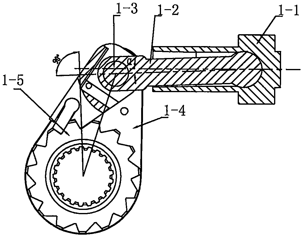
technical field [0001] The invention relates to a torque wrench, in particular to a hydraulic torque wrench. Background technique [0002] Existing hydraulic torque wrenches such as figure 1 As shown, it includes a ratchet mechanism and a loading mechanism. The loading mechanism is a hydraulic cylinder. The hydraulic cylinder includes a piston 1-1 and a push rod 1-2 hinged to it. In the ratchet mechanism, the drive plate 1-4 for driving the ratchet and the push rod 1- The outer end of 2 is hinged by the driving pin 1-3, and the loading mechanism converts the thrust of the piston 1-1 through the transmission of the push rod 1-2 into torque output to the torque of the ratchet 1-5. This kind of hydraulic torque wrench has a large torque output value, but there is a problem that as the position of the piston 1-1 in the hydraulic cylinder changes, the angle α formed between the axis of the ejector rod 1-2 and the axis of the piston 1-1 It will also change accordingly. When the ...

Claims


Application Information

Patent Timeline
IPC IPC(8): B25B21/00
CPCB25B21/005
Inventor 宋新潮张振平武永中袁博徐英杰
Owner AVIC SHAANXI DONGFANG AVIATION INSTR
Learn More