
Punching clamp for cam shaft housing

A punching fixture and camshaft technology, applied in the direction of clamping, manufacturing tools, supports, etc., can solve the problems of product quality not meeting the installation requirements, wasting time, inaccurate centering, and inconvenient round centering, etc., to achieve Reasonable and compact structure, convenient operation and precise size

Active Publication Date: 2017-02-08
上海伟奕传动轴配件有限公司
View PDF7 Cites 1 Cited by
  • Summary
  • Abstract
  • Description
  • Claims
  • Application Information

AI Technical Summary

Problems solved by technology

[0002] The engine camshaft is one of the main parts of the engine running. The outer side of the camshaft generally needs to be installed with a cover. Each punching hole needs to be clamped and centered once after each hole is punched, and the circular centering is inconvenient, which not only wastes time but also makes the centering inaccurate, and the product quality cannot meet the installation requirements, which is a waste of time and Reduced work efficiency

Method used


Image

  • Punching clamp for cam shaft housing

Examples


Embodiment Construction

[0013] The present invention will be further explained below in conjunction with the accompanying drawings and specific embodiments. It should be understood that the following specific embodiments are only used to illustrate the present invention and are not intended to limit the scope of the present invention. It should be noted that the words "front", "rear", "left", "right", "upper" and "lower" used in the following description refer to the directions in the drawings, and the words "inner" and "outer ” refer to directions towards or away from the geometric center of a particular part, respectively.

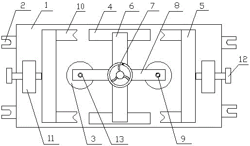
[0014] As shown in the figure, a camshaft cover drilling jig according to the present invention includes a base 1, connecting holes 2 are provided on both sides of the base 1, two workbenches 3, a limit block 4 and Block 5, two limit blocks 4 are arranged on the front and rear ends of the upper plane of the base 1, the limit block 4 is provided with a crossbeam 6 connected to e...


PUM


Abstract

The invention discloses a punching clamp for a cam shaft housing. The punching clamp comprises a base. Two working tables, two spacing blocks and two stop blocks are arranged on the upper pane of the base. The two spacing blocks are arranged at the front end and the rear end of the upper plane of the base. Cross beams connected with each other are arranged on the spacing blocks. A first rotary pressing part is arranged between the cross beams. A pressing plate is arranged below the first rotary pressing part. Through holes are formed in two sides of the pressing plate. The two stop blocks are arranged on two sides of the upper pane of the base. V-shaped blocks are arranged at the front part and the rear part of the inner side of each stop block. Fixed blocks are arranged at the outer sides of the stop blocks. A second rotary pressing part is arranged on each fixed block, and is opposite to the middle of each corresponding stop block. Each working table is arranged between the corresponding V-shaped blocks. Positioning rods are arranged on the working tables, and are arranged in the through holes. The punching clamp is reasonable and compact in structure, and convenient to operate, and realizes all-directional clamping. After being punched, the cam shaft housing is accurate in size and position. A cam shaft is conveniently mounted. Two cam shaft housings can be processed at one step, so that the efficiency is doubled.

Description

technical field [0001] The invention belongs to the technical field of fixtures, and in particular relates to a camshaft cover punching fixture. Background technique [0002] The engine camshaft is one of the main parts of the engine running. The outer side of the camshaft generally needs to be installed with a cover. Each punching hole needs to be clamped and centered once after each hole is punched, and the circular centering is inconvenient, which not only wastes time but also makes the centering inaccurate, and the product quality cannot meet the installation requirements, which is a waste of time and Reduced work efficiency. Contents of the invention [0003] In order to solve the above problems, the invention discloses a camshaft cover punching jig, which has a reasonable and compact structure, is convenient to operate, has precise dimensions and positions after drilling, and facilitates the installation of the camshaft. [0004] To achieve the above object, the te...

Claims


Application Information

Patent Timeline
Patent Type & Authority Applications(China)
IPC IPC(8): B23Q3/06
CPCB23Q3/062B23Q3/069
Inventor 郭曙光
Owner 上海伟奕传动轴配件有限公司
Learn More