
Laser cutting machine and processing method for processing automotive interior parts

A technology for laser cutting machines and automotive interior parts, applied in the field of automobile manufacturing, can solve the problems of lack of mechanical fixing devices, inability to continuously cut workpieces, fulcrum, and joint fatigue, etc. good condition

Active Publication Date: 2018-06-19
常州涵洋高分子材料科技有限公司
View PDF5 Cites 1 Cited by
  • Summary
  • Abstract
  • Description
  • Claims
  • Application Information

AI Technical Summary

Problems solved by technology

[0002] At present, many automotive interior parts are cut by laser, which has the advantages of fast cutting speed, smooth cutting surface, high cutting precision, not affected by the shape of the workpiece, and can cut a variety of materials. The cutting method is to first fix the formed automotive workpiece On the laser cutting fixture, a robot is used to control the laser cutting machine to cut. Many cutting robots currently in use are fixed on the ground in the form of cantilever beams. Their fulcrums and nodes are prone to fatigue, and their operation stability is poor. The cutting range is limited. When encountering a long workpiece, the entire workpiece cannot be cut continuously at one time. There are no protective measures around many cutting devices. Due to the high brightness of the laser cutting, it has a greater impact on external interference. Many cutting fixtures lack mechanical fixing devices, and manual fixing is required, which requires a long fixing time

Method used


Image

  • Laser cutting machine and processing method for processing automotive interior parts
  • Laser cutting machine and processing method for processing automotive interior parts
  • Laser cutting machine and processing method for processing automotive interior parts

Examples


Embodiment Construction

[0032] Embodiments of the technical solutions of the present invention will be described in detail below in conjunction with the accompanying drawings. The following examples are only used to illustrate the technical solutions of the present invention more clearly, and therefore are only examples, rather than limiting the protection scope of the present invention.

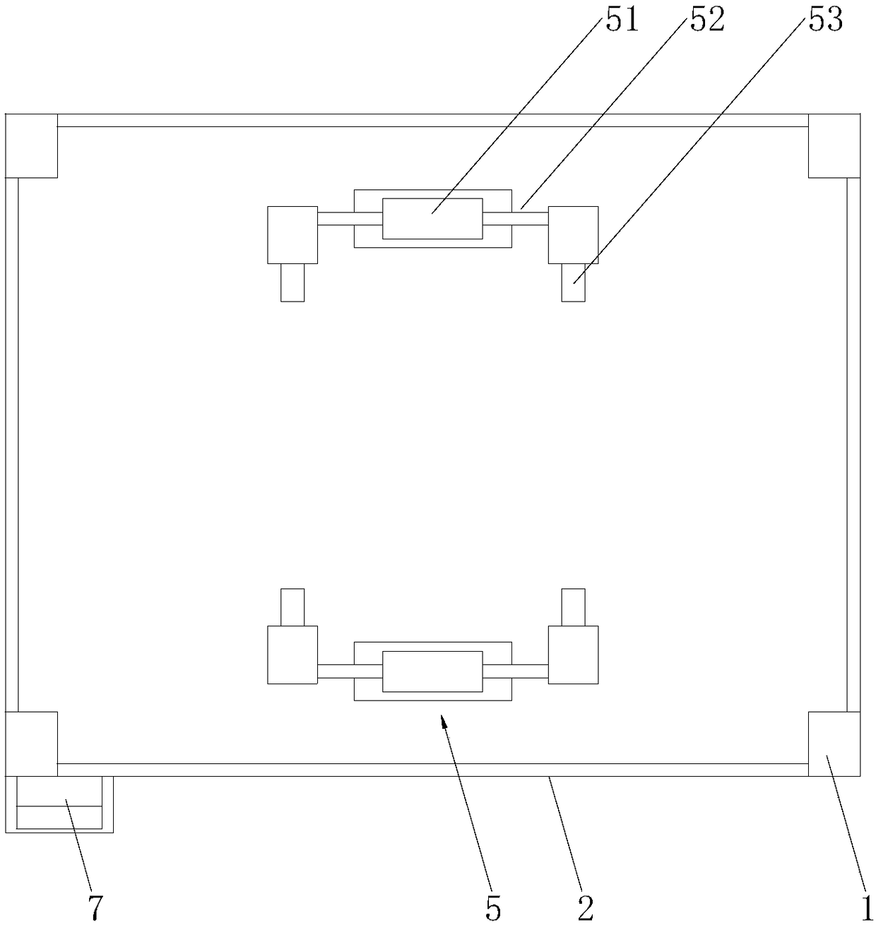
[0033] Such as Figure 1 to Figure 10 As shown, it includes a machine base 9, a support frame 1, a laser cutting enclosure device 2, an upper moving device 3, a cutting robot 4, a fixing device 5, a camera device 6, and an electric control device 7; the support frame 1 is installed on the machine base 9 , the support frame 1 includes a column 11 perpendicular to the ground, a beam 12 installed on the column 11 and a track beam 13 installed on the beam 12, and the track beam 13 includes a first track beam 131 and a second track beam 132 .

[0034] The upper moving device 3 is supported by the support frame 1 and i...


PUM


Abstract

The invention discloses a laser cutting machine used for machining an automobile interior trim part. The cutting machine comprises a machine base, a supporting frame, an upper moving device, a cutting robot, a laser cutting enclosure device, a fixing device, a camera device and an electric control device; the supporting frame is mounted on the machine base, the upper moving device is supported above the machine base through the supporting frame, the upper moving device comprises a gear and rack transmission system driven by a stepping motor, the upper end of the cutting robot is connected with the lower end of the upper moving device, the fixing device is arranged on the machine base and close to the laser cutting enclosure device, the camera device is arranged on a cutting machine inlet and located on the upper portion of the supporting frame, and the electric control device is arranged outside the supporting frame; the laser cutting machine used for machining the automobile interior trim part can increase the cutting range, the laser cutting enclosure device and the cutting clamp fixing device are arranged, the influence on the surroundings is reduced, the fixing time of a cutting clamp is shortened, and the production efficiency is improved.

Description

technical field [0001] The invention relates to the field of automobile manufacturing, in particular to a laser cutting machine and a processing method for processing automobile interior parts. Background technique [0002] At present, many automotive interior parts are cut by laser, which has the advantages of fast cutting speed, smooth cutting surface, high cutting precision, not affected by the shape of the workpiece, and can cut a variety of materials. The cutting method is to first fix the formed automotive workpiece On the laser cutting fixture, a robot is used to control the laser cutting machine to cut. Many cutting robots currently in use are fixed on the ground in the form of cantilever beams. Their fulcrums and nodes are prone to fatigue, and their operation stability is poor. The cutting range is limited. When encountering a long workpiece, the entire workpiece cannot be cut continuously at one time. There are no protective measures around many cutting devices. D...

Claims


Application Information

Patent Timeline
Patent Type & Authority Patents(China)
IPC IPC(8): B23K26/38B23K26/70
CPCB23K26/38B23K26/702B23K2101/006
Inventor 郭洪宇
Owner 常州涵洋高分子材料科技有限公司
Learn More