


Quick Research
Generate reliable direction feasibility study reports for your R&D in just a few steps.

Technical Q&A
Discover and master advanced knowledge NOW. Basics, ideas, possibilities, all at once.

Find Solutions
As an expert in R&D theories, this can generate solutions to your technical problems instantly.

Evaluate Feasibility
Analyze your overall solution with one click, know your potential R&D risks in advance.

Monitor Landscape
Get weekly tech updates, stay abreast of the latest tech innovations and key insights.
Detection device for composite steel belt of elevator
A detection device and technology of composite steel are applied in the field of elevator traction components to achieve the effects of convenient operation, ensuring operation safety and eliminating fault risks.
- Summary
- Abstract
- Description
- Claims
- Application Information
AI Technical Summary
Problems solved by technology
Method used
Image

Examples
Embodiment 1
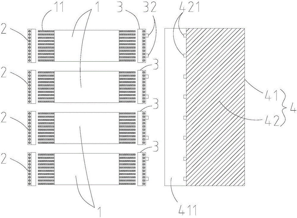
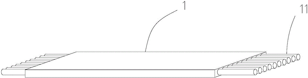
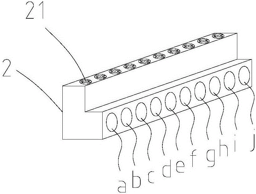
[0025] see Figures 1 to 4 , a detection device for an elevator composite steel belt, comprising a first electrical connector 2 , a second electrical connector 3 and an electrical signal analysis device 4 . Among them, there are four first electrical connectors 2 and four second electrical connectors 3 , and one first electrical connector 2 and one second electrical connector 3 can be used to connect a composite steel strip 1 . Before the detection of the composite steel strip 1 , the non-metallic wrapping layers at the first and last ends need to be stripped off to expose the first and the ends of the multi-strand steel core 11 . The first end of each steel core 11 in the composite steel strip 1 is electrically connected to the first electrical connector 2 , and the second electrical connector 3 at the end is respectively electrically connected. Each second electrical connector 3 is provided with two connection contacts 32 , and the two connection contacts 32 can be correspo...
Embodiment 2
[0035] Such as image 3 , 4As shown in and 6, the structure of this embodiment is basically the same as that of Embodiment 1, the difference is that in this embodiment, the first potential connection points on the first electrical connector 2 are connected in groups of two, and the second electrical connector 3 includes A second potential connection point is connected to one of the connection contacts 32 on the second electrical connector 3, wherein another second potential connection point is connected to another connection contact 32 on the second electrical connector 3, and the rest The second potential connection points are connected in pairs, and all the steel cores 11 of the same composite steel strip 1 are electrically connected to all the first potential connection points and all the second potential connection points respectively, and then connected end to end to form a pure series circuit. Specifically, in this embodiment, on the first electrical connector 2, a is c...
Embodiment 3
[0037] Such as image 3 , 4 As shown in and 7, the structure of this embodiment is basically the same as that of Embodiment 1, the difference is that all the second electrical connection points k, l, m, n, o, p, q of the second electrical connector 3 of this embodiment , r, s, t are equipotentially connected to one of the connection contacts 32, and all the first points of the first electrical connector 2 are connected to points a, b, c, d, e, f, g, h, i, After the equipotential connection, it is connected with another connection contact 32 through the electrical connector 5, and all the steel cores 11 of the same composite steel strip 1 are respectively electrically connected with all the first potential connection points and all the second potential connection points to form a pure parallel circuit.
PUM
 Abstract
Description
Claims
Application Information
 - R&D Engineer
- R&D Manager
- IP Professional
- Industry Leading Data Capabilities
- Powerful AI technology
- Patent DNA Extraction
Browse by: Latest US Patents, China's latest patents, Technical Efficacy Thesaurus, Application Domain, Technology Topic, Popular Technical Reports.
© 2024 PatSnap. All rights reserved.Legal|Privacy policy|Modern Slavery Act Transparency Statement|Sitemap|About US| Contact US: help@patsnap.com