Multi-stage flow guide device

A technology of a deflector and a deflector, which is applied to the components of the pumping device for elastic fluids, non-variable-capacity pumps, machines/engines, etc., can solve the problems of low performance and easy eddy current resistance in the airflow. , to achieve the effect of optimizing structural design, reducing fluid eddy current and wind resistance, and reducing temperature

Inactive Publication Date: 2017-02-01
GUANGDONG WELLING ELECTRIC MACHINE MFG +1
View PDF8 Cites 10 Cited by
  • Summary
  • Abstract
  • Description
  • Claims
  • Application Information

AI Technical Summary

Problems solved by technology

[0002] In the structure of the vacuum cleaner in the related art, the fan rotates under the drive of the driving device, and a negative pressure is formed in the sealed casing to suck the dust into the dust collecting device to achieve the cleaning effect. The speed is generally between 60000-80000rpm, and the diffuser is generally used to introduce the fluid into the center of the drive device for heat dissipation. The air flow is easy to generate eddy currents and has a large resistance, and the performance is generally low.

Method used


Image

  • Multi-stage flow guide device
  • Multi-stage flow guide device
  • Multi-stage flow guide device

Examples


Embodiment Construction

[0030] Embodiments of the present invention are described in detail below, examples of which are shown in the drawings, wherein the same or similar reference numerals designate the same or similar elements or elements having the same or similar functions throughout. The embodiments described below by referring to the figures are exemplary and are intended to explain the present invention and should not be construed as limiting the present invention.

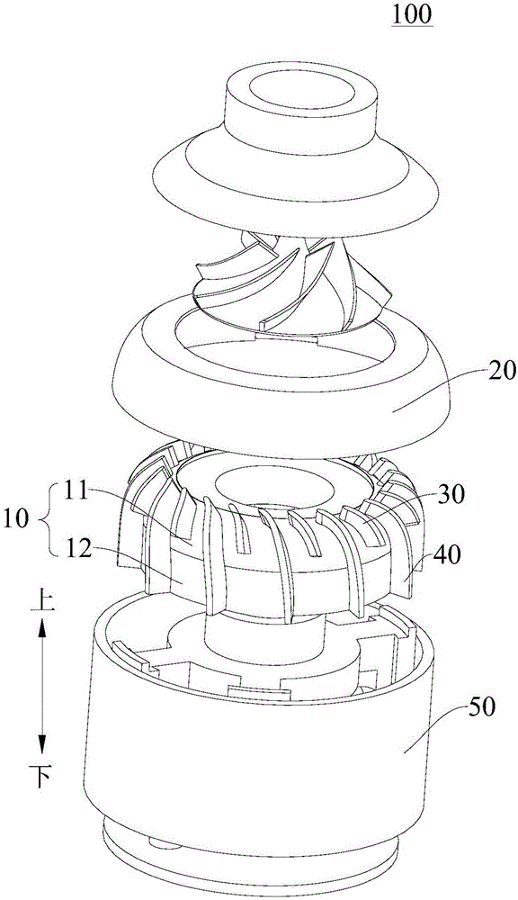
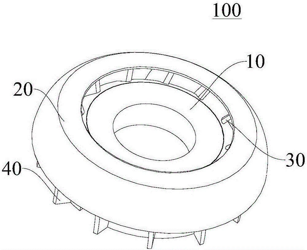
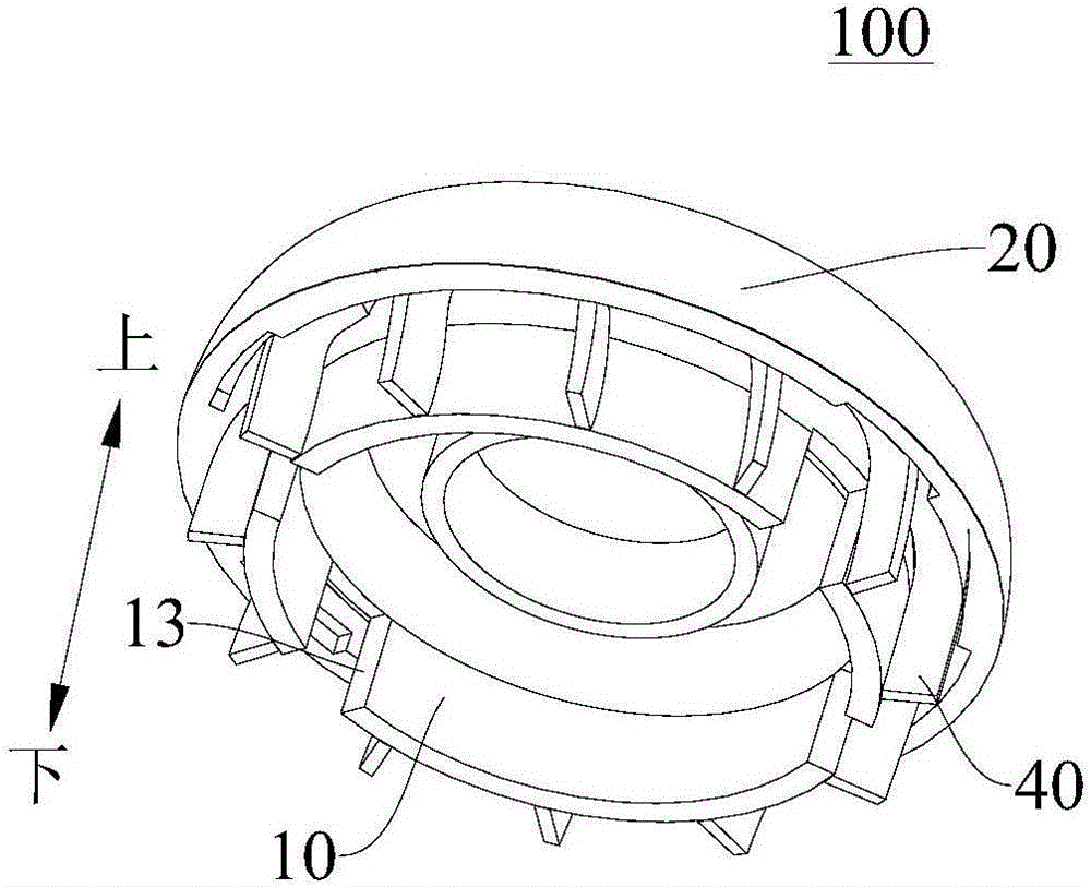
[0031] Attached below figure 1 to attach Figure 7 The multi-stage flow guide device 100 according to the embodiment of the present invention will be described in detail.

[0032] According to the embodiment of the present invention, the multi-stage flow guide device 100 includes a base body 10, a guide wind cover 20, a plurality of first helical blades 30 and a plurality of second helical blades 40, the base body 10 is roughly formed in a column shape, and the guide wind The cover 20 is arranged on the seat body 10, the wind g...


PUM


Abstract

The invention discloses a multi-stage flow guide device. The multi-stage flow guide device comprises a seat, a flow guide fan cover, a plurality of first helical blades and a plurality of second helical blades, wherein the flow guide fan cover is arranged on the seat, is roughly annular and is located at one end of the seat, an air chamber is defined between the inner wall surface of the flow guide fan cover and the outer wall surface of the seat, an air chamber inlet is defined by spacing the flow guide fan cover and one end of the seat, the plurality of first helical blades are arranged on the outer wall surface of the seat at intervals in the circumferential direction of the seat and located in the air chamber, the plurality of second helical blades are arranged on the outer wall surface of the seat at intervals in the circumferential direction of the seat and are spaced and staggered with the first helical blades, one end of each second helical blade is located in the air chamber, the other end extends out of the air chamber, and an air chamber outlet is defined between the other ends of every two adjacent second helical blades. According to the multi-stage flow guide device disclosed by the embodiment of the invention, the vortex and the resistance of a fluid are reduced effectively, and the heat dissipation effect of a driving device is improved.

Description

technical field [0001] The invention relates to the technical field of fluid conveying machinery, in particular to a multi-stage flow guiding device applied to fans of vacuum cleaners or hoods. Background technique [0002] In the structure of the vacuum cleaner in the related art, the fan rotates under the drive of the driving device, and a negative pressure is formed in the sealed casing to suck the dust into the dust collecting device to achieve the cleaning effect. The speed is generally between 60000-80000rpm, and the diffuser is generally used to introduce the fluid into the center of the drive device for heat dissipation. The airflow is prone to eddy currents and has a large resistance, and the performance is generally low. Contents of the invention [0003] The present invention aims to solve one of the above-mentioned technical problems at least to a certain extent. [0004] Therefore, the present invention proposes a multi-stage flow guiding device, which not on...

Claims


Application Information

Patent Timeline
Patent Type & Authority Applications(China)
IPC IPC(8): F04D29/44
CPCF04D29/441
Inventor 蒋婷婷冯国平
Owner GUANGDONG WELLING ELECTRIC MACHINE MFG
Why Eureka
Try Eureka