A mechanical linkage anti-theft lock

An anti-theft lock and mechanical technology, applied in the field of locks, can solve the problems of difficult processing, inconvenient operation and high cost, etc., and achieve the effects of increasing safety and reliability, facilitating maintenance and operation, and increasing flexibility of use

Active Publication Date: 2018-12-18
江苏星爵实业有限公司
View PDF1 Cites 1 Cited by
  • Summary
  • Abstract
  • Description
  • Claims
  • Application Information

AI Technical Summary

Problems solved by technology

The basic structures of existing mechanical anti-theft locks are basically similar. The lock tongue has developed from a single direction to a three-way five-tongue mechanical anti-theft lock. The lock cylinder directly pushes the lock tongue. The design is not reasonable enough, the structure is complicated, the anti-theft performance is not good, and the processing is relatively difficult, and it occupies a relatively large space. At the same time, there are disadvantages such as high failure rate, high cost, and inconvenient operation and use.

Method used


Image

  • A mechanical linkage anti-theft lock
  • A mechanical linkage anti-theft lock
  • A mechanical linkage anti-theft lock

Examples


Embodiment Construction

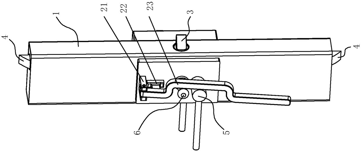
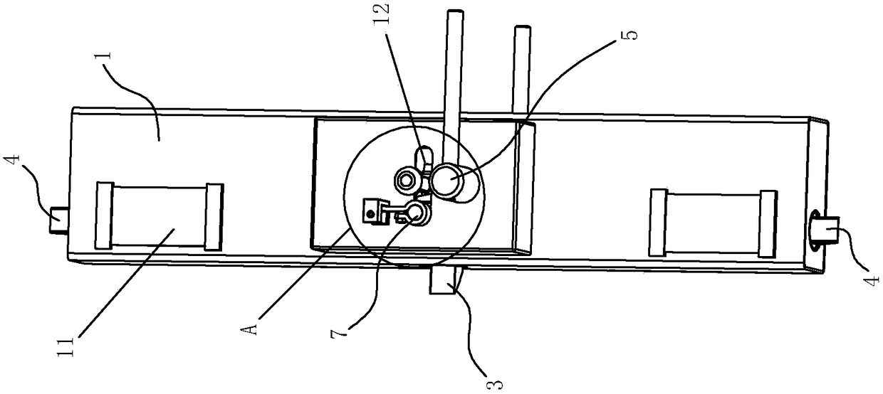
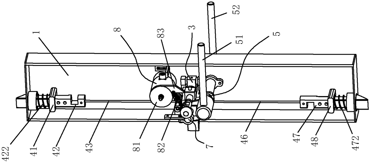
[0037] Such as Figure 1 to Figure 18 As shown, a mechanical linkage anti-theft lock of the present invention includes a lock housing 1, an unlocking lever assembly 5, a main tongue assembly 3, an auxiliary tongue assembly 4 and a lock cylinder assembly 8, and the lock cylinder assembly 8 is positioned in the lock housing 1 in.

[0038] Such as Figure 9 to Figure 11 As shown, the main bolt assembly 3 includes a main bolt 32, a main bolt post 33 and a main bolt positioning seat 31 for positioning the main bolt 32, and the main bolt positioning seat 31 is positioned on the lock housing 1 and located below the lock cylinder assembly 8; the main bolt 32 includes a main bolt 323, a main bolt 321 and a return spring I 322, the main bolt 323 passes through the main bolt positioning seat 31, and the main bolt 321 is connected to At the front end of the main tongue bar 323 and can extend out of the lock housing 1, the return spring I322 is sleeved on the outside of the main tongue b...


PUM


Abstract

The invention discloses a mechanical linkage antitheft lock and belongs to the technical field of locks. The mechanical linkage antitheft lock comprises a lock shell, an unlocking shift lever assembly, a main bolt assembly, an auxiliary bolt assembly and a lock cylinder assembly. The main bolt assembly comprises a main spring bolt, a main spring bolt column and a main spring bolt positioning base, and the main spring bolt column is provided with a limiting column. A locking block of the lock cylinder assembly abuts against the edge of the limiting column. The unlocking shift lever assembly comprises a shift lever shaft, a shift lever shaft sleeve and a shift lever handle. A spring bolt shift lever is connected to the middle of the shift lever shaft and abuts against the edge of the main spring bolt column, and the main spring bolt can retract inwards by wrenching the shift lever handle. The auxiliary bolt assembly comprises an upper spring bolt, a lower spring bolt, a pulley and a steel wire rope, one end of the steel wire rope is connected with the upper spring bolt and the lower spring bolt, the other end of the steel wire rope bypasses the pulley and is connected with the main spring bolt, and when the main spring bolt retracts inwards, the steel wire rope enables the upper spring bolt and the lower spring bolt to retract into the lock shell at the same time. According to the mechanical linkage antitheft lock, a linkage mechanism is simple, machining and assembling are convenient, operation is reliable, operation is convenient and flexible, multiple anti-prying and antitheft functions are achieved, and the antitheft lock can be effectively prevented from being unlocked violently by lawbreakers.

Description

technical field [0001] The invention relates to the technical field of locks, in particular to a mechanical linkage anti-theft lock. Background technique [0002] Anti-theft locks have a very close relationship in human life. As an indispensable tool in people's daily life, it is related to the safety of every family, unit and public place. There are also higher requirements. At present, the anti-theft locks on the market have various structures and styles, which can generally be divided into two categories: mechanical linkage anti-theft locks and electronic anti-theft locks. Mechanical linkage anti-theft locks rely on the interaction between machines to open and close the anti-theft locks. High reliability. The basic structures of existing mechanical anti-theft locks are basically similar. The lock tongue has developed from a single direction to a three-way five-tongue mechanical anti-theft lock. The lock cylinder directly pushes the lock tongue. The design is not reason...

Claims


Application Information

Patent Timeline
Patent Type & Authority Patents(China)
IPC IPC(8): E05B63/14E05B53/00E05B15/10E05B3/00E05B17/00
CPCE05B3/00E05B15/108E05B17/00E05B53/005E05B63/146
Inventor 杨晶晶
Owner 江苏星爵实业有限公司
Why Eureka
Try Eureka