
Mobile phone shell with storage function

A mobile phone shell and mobile phone technology, applied in the direction of telephone structure, telephone communication, electrical components, etc., can solve the problems of single function, no information storage function, simple appearance and protection of mobile phones, etc., to achieve expanded use scenarios and simple structure , low cost effect

Inactive Publication Date: 2017-01-25
BEIJING ZHIMO SCI & TECH
View PDF6 Cites 1 Cited by
  • Summary
  • Abstract
  • Description
  • Claims
  • Application Information

AI Technical Summary

Problems solved by technology

[0005] The technical problem to be solved by the present invention is that the mobile phone protective case on the market is only purely beautiful and protects the mobile phone, does not have the function of information storage, and has a single function

Method used


Image

  • Mobile phone shell with storage function
  • Mobile phone shell with storage function
  • Mobile phone shell with storage function

Examples


Embodiment 1

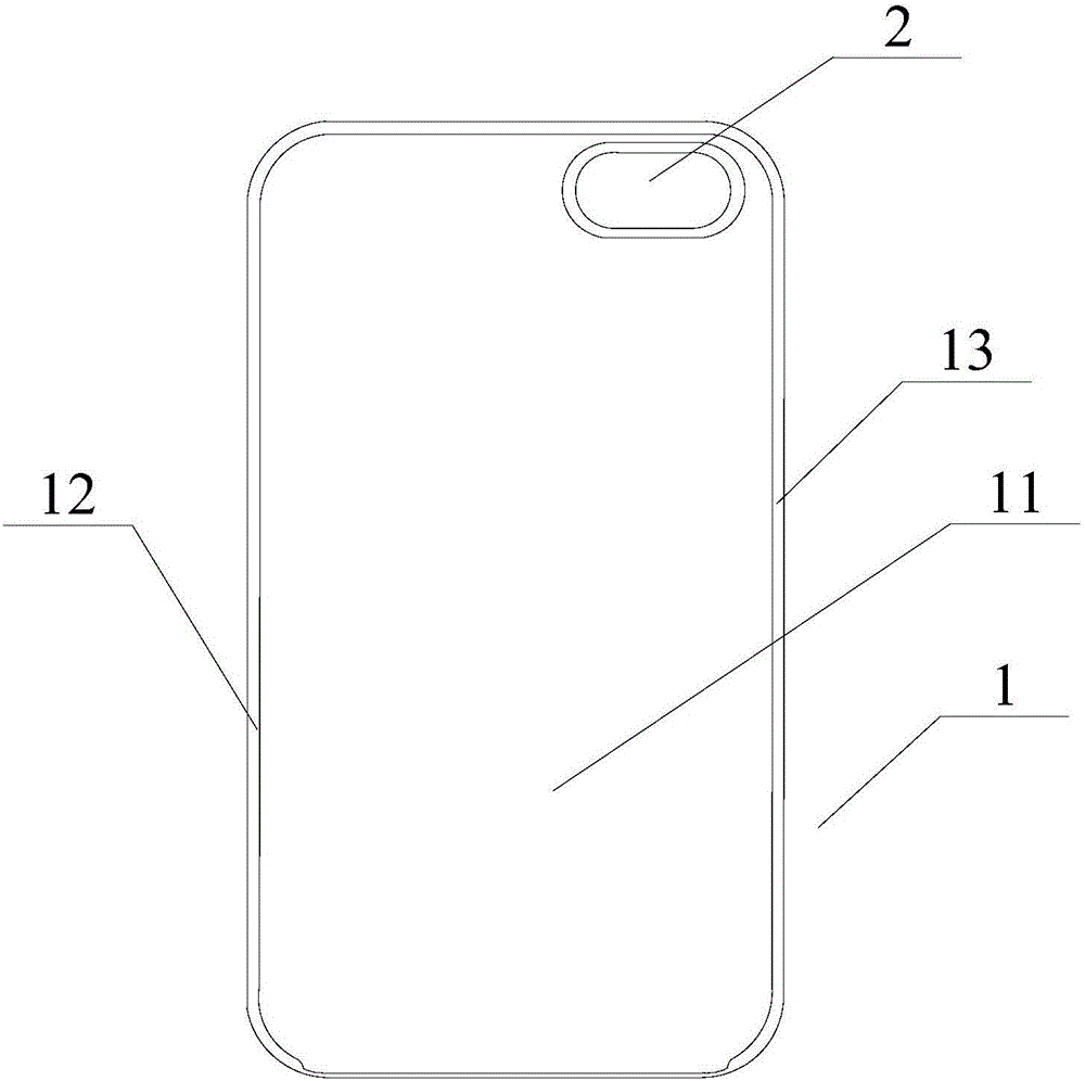
[0026] Such as figure 1 As shown, the present invention provides a mobile phone case with a storage function, including: a case 1 and a sliding mechanism integrally formed with the case 1 .

[0027] The housing 1 at least includes a base plate 11, a left side wall 12 and a right side wall 13, the left side wall 12 is provided with a volume hole, and the edges of the left side wall 12 and the right side wall 13 are respectively provided with flip buttons for fastening the mobile phone. side; the upper left corner of the bottom plate 11 is provided with a camera hole 2. The housing 1 is a polymer material, specifically rubber or plastic.

[0028] It can also include an upper side wall and a lower side wall that are arc-shaped connected with the left and right side walls. The upper side wall and the lower side wall are respectively provided with earphone holes and charging holes, etc., or are arranged on the upper side wall or the lower side wall at the same time. superior.

...

Embodiment 2

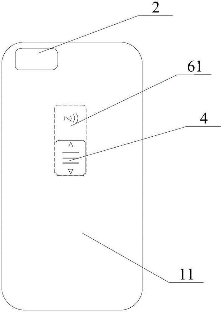
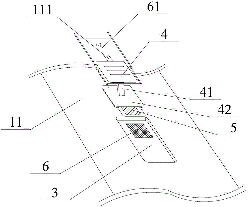
[0035] Such as Figure 5 As shown, another embodiment provided by the present invention differs from the above-mentioned embodiment in that: the middle area of ​​the base plate 11 is provided with an open square groove 7, and its open end is detachably connected to a sealing block 8, the sealing block A conductive chute 111 ′ is provided in the lower end area of ​​the 8 , the sliding mechanism is slidably provided on the chute 111 ′, and the NFC mark 61 is provided on the upper surface of the sealing block 8 . This structure is designed to facilitate the user to remove the sliding mechanism and replace the NFC memory chips 5 of different sizes according to the needs.


PUM


Abstract

The invention discloses a mobile phone shell with a storage function. The mobile phone shell comprises a shell body and a sliding mechanism which is arranged on the shell body in a sliding manner, wherein the shell body comprises a bottom plate, a left side wall and a right side wall; edges of the left side wall and the right side wall are inwards provided with turning edges for fastening a mobile phone respectively; the bottom plate is provided with a built-in cavity; a first sliding groove is formed in the bottom plate at the upper side of the cavity; the sliding mechanism is arranged on the bottom plate through the first sliding groove in a manner of sliding up and down; the upper end region on the bottom surface in the cavity is an NFC (Near Field Communication) mobile phone induction region; and an NFC storage chip, which is wirelessly connected with the mobile phone, is arranged at the lower end of the sliding mechanism. According to the mobile phone shell with the storage function, the mobile phone shell is combined with the NFC storage chip, so that the mobile phone shell has a certain information storage function; meanwhile, the NFC storage chip is read through an NFC reading function of the mobile phone, so that exchange of information and instructions is realized and an application scene of the mobile phone shell is extremely expanded; and the mobile phone shell is low in cost, simple in structure and wide in applicable range.

Description

technical field [0001] The invention relates to a protective case for a mobile phone, in particular to a mobile phone case with a storage function. Background technique [0002] With the accelerated development of science and technology, the science and technology beauty industry has emerged as a new type of industry. The generalization and popularization of various middle and high-end mobile phone internal chain users. Seeing the development prospects of global mobile phone cases, manufacturers of mobile phone cases have sprung up like mushrooms after rain. These companies produce mobile phone cases in various materials, while also focusing on the aesthetics, personality, and quality of the mobile phone case. The mobile phone protective case not only serves as an ornament to make the mobile phone a landscape, but also protects the mobile phone, anti-drop, waterproof and shockproof. [0003] But at present, the ordinary mobile phone case only plays the role of pure beauty...

Claims


Application Information

Patent Timeline
Patent Type & Authority Applications(China)
IPC IPC(8): H04M1/18H04M1/02
CPCH04M1/026H04M1/18
Inventor 张明军
Owner BEIJING ZHIMO SCI & TECH
Learn More