Eureka AIR delivers breakthrough ideas for toughest innovation challenges, trusted by R&D personnel around the world.

Drive circuit, array substrate and liquid crystal display

A technology for driving circuits and array substrates, applied in the fields of driving circuits, array substrates and liquid crystal displays, can solve problems such as difficulty in providing gate signals and the like

Inactive Publication Date: 2017-01-25
WUHAN CHINA STAR OPTOELECTRONICS TECH CO LTD
View PDF4 Cites 10 Cited by
  • Summary
  • Abstract
  • Description
  • Claims
  • Application Information

AI Technical Summary

Problems solved by technology

For flexible OLED displays, due to the need to compensate threshold voltage and mobility, more gate signals are required, so it becomes very difficult to provide gate signals from external ICs

Method used


Image

  • Drive circuit, array substrate and liquid crystal display
  • Drive circuit, array substrate and liquid crystal display
  • Drive circuit, array substrate and liquid crystal display

Examples


Embodiment Construction

[0023] The following will clearly and completely describe the technical solutions in the embodiments of the present invention with reference to the accompanying drawings in the embodiments of the present invention. Obviously, the described embodiments are only part of the embodiments of the present invention, not all of them. Based on the embodiments of the present invention, all other embodiments obtained by persons of ordinary skill in the art without making creative efforts belong to the protection scope of the present invention.

[0024] In addition, the following descriptions of the various embodiments refer to the attached drawings to illustrate specific embodiments in which the present invention can be implemented. The directional terms mentioned in the present invention, for example, "upper", "lower", "front", "rear", "left", "right", "inner", "outer", "side", etc., only is to refer to the direction of the attached drawings. Therefore, the direction terms used are for ...


PUM


Abstract

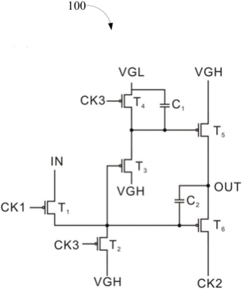
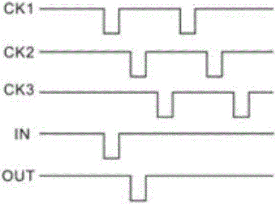
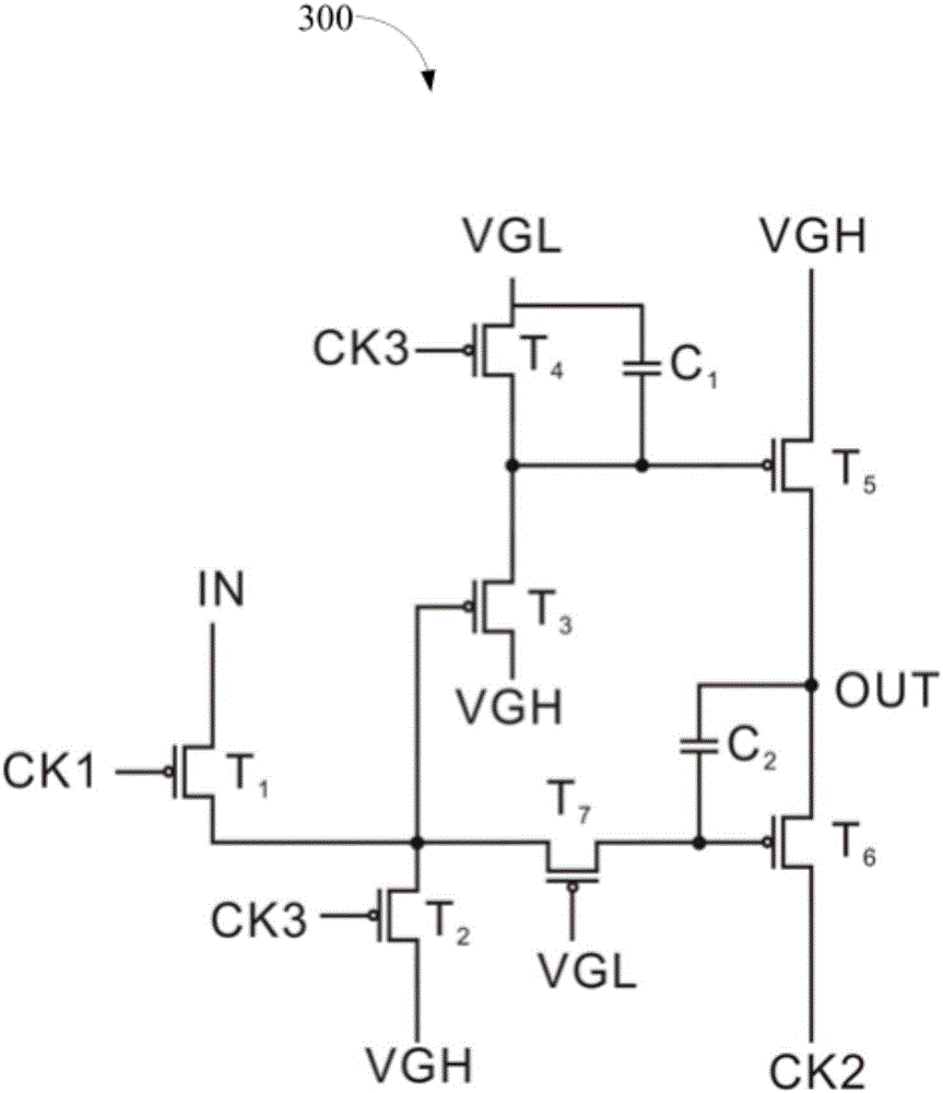
The invention provides a drive circuit which comprises the first to the sixth transistors, a high level end and a low level end, wherein a grid electrode of the first transistor is used as a first clock signal end; a drain electrode of the first transistor is used as a voltage input end; a source electrode of the first transistor is connected to the drain electrode of the second transistor, the grid electrode of the third transistor and the grid electrode of the sixth transistor; the grid electrode of the second transistor is used as a third clock signal end; the source electrode of the second transistor is connected to the high level end; the drain electrode of the third transistor is connected to the source electrode of the fourth transistor and the grid electrode of the fifth transistor; the source electrode of the third transistor is connected with the high level end; the grid elected of the fourth transistor is used as the third clock signal end; the drain electrode of the third transistor is connected with the low level end; the drain electrode of the fifth transistor is connected with the high level end; the source electrode of the fifth transistor is connected to the drain electrode (voltage output end) of the sixth transistor; the source electrode of the sixth transistor is used as the second clock signal end; and the voltage output end outputs a voltage signal obtained after displacing the input voltage. The drive circuit provided by the invention can save the manufacture procedure, and the production efficiency is improved.

Description

technical field [0001] The invention relates to the field of display technology, in particular to a driving circuit, an array substrate and a liquid crystal display. Background technique [0002] GOA (Gate Driver On Array, array substrate row drive technology) allows the gate circuit to be integrated on the array substrate, which can save the integrated chip of the gate potential signal. For flexible OLED displays, due to the need to compensate the threshold voltage and mobility, more gate signals are needed, so it becomes very difficult to provide gate signals from an external integrated circuit. Contents of the invention [0003] The purpose of the present invention is to provide a driving circuit to simplify and save manufacturing process and improve production efficiency. [0004] Another object of the present invention is to provide a liquid crystal display. [0005] In order to achieve the above object, the embodiment of the present invention provides the following...

Claims


Application Information

Patent Timeline
Patent Type & Authority Applications(China)
IPC IPC(8): G09G3/36
CPCG09G3/3677
Inventor 李骏
Owner WUHAN CHINA STAR OPTOELECTRONICS TECH CO LTD
Why Eureka
Eureka Blog
Learn More