
Automotive blind spot detection system and method adopting microwave radar sensor and ultrasonic sensors

A microwave radar and detection system technology, applied in the directions of radio wave measurement system, sound wave re-radiation, radio wave reflection/re-radiation, etc. system detection performance gap and other problems, to reduce costs, improve detection performance, and good functional scalability.

Active Publication Date: 2017-01-25
XIAMEN AUTOSTAR ELECTRONICS CO LTD
View PDF6 Cites 17 Cited by
  • Summary
  • Abstract
  • Description
  • Claims
  • Application Information

AI Technical Summary

Problems solved by technology

The detection distance (range) of the ultrasonic blind spot detection system is too small, and there are serious deficiencies
At the same time, even though everyone is currently working hard to develop a long-distance ultrasonic blind spot detection system, its farthest detection distance is difficult to exceed ten meters; moreover, the detection distance of the ultrasonic sensor is greatly increased, and the detection response speed of the ultrasonic sensor will be significantly reduced. Compared with the blind zone system, the detection performance of the ultrasonic blind zone system still has a significant gap
[0011] However, the cost of a single ultrasonic sensor is less than one tenth of that of a single microwave radar sensor, so the cost of an ultrasonic blind spot detection system equipped with four ultrasonic sensors is less than four times that of a microwave radar blind spot detection system equipped with two microwave radar sensors. one-third

Method used


Image

  • Automotive blind spot detection system and method adopting microwave radar sensor and ultrasonic sensors
  • Automotive blind spot detection system and method adopting microwave radar sensor and ultrasonic sensors
  • Automotive blind spot detection system and method adopting microwave radar sensor and ultrasonic sensors

Examples


Embodiment Construction

[0098] The present invention will now be described more fully with reference to the accompanying drawings, in which exemplary embodiments of the invention are shown. This invention may, however, be embodied in many different forms and should not be construed as limited to the exemplary embodiments set forth herein. Rather, these embodiments are provided so that this disclosure will be thorough and complete, and will fully convey the scope of the invention to those skilled in the art.

[0099] For ease of description, spatially relative terms such as "upper," "lower," "left," and "right" may be used herein to describe the relationship of one element or feature relative to another element or feature shown in the figures. It will be understood that the spatial terms are intended to encompass different orientations of the device in use or operation in addition to the orientation depicted in the figures. For example, if the device in the figures is turned over, elements described ...


PUM


Abstract

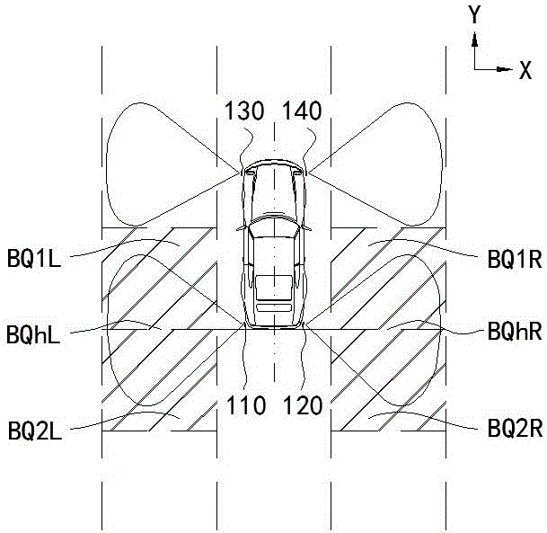
The invention discloses an automotive blind spot detection system and method adopting a microwave radar sensor and ultrasonic sensors. The automotive blind spot detection system comprises the microwave radar sensor arranged in the middle of the tail end of an automobile and the ultrasonic sensors symmetrically arranged on two sides of the automobile, wherein the detection zone of the microwave radar sensor covers the rear ends of blind spots, for abutting lanes, of exterior rear-view mirrors and part of visible areas behind the rear ends of the blind spots of the automobile; the detection zones of the ultrasonic sensors cover the front ends of the blind spots for the abutting lanes, of the exterior rear-view mirrors of the automobile; the detection zones of the microwave radar sensor and the ultrasonic sensors wholly cover the blind spots of the exterior rear-view mirrors of the automobile, extending areas of the rear ends of the blind spots and extending detection areas at the tail end of the automobile. The detection performance of the blind spot detection system is guaranteed effectively or even improved, the system cost is reduced effectively, the function extensibility of the system is good, and one preferred scheme is provided.

Description

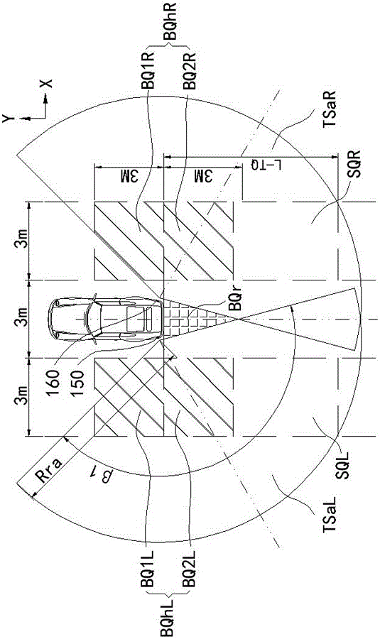
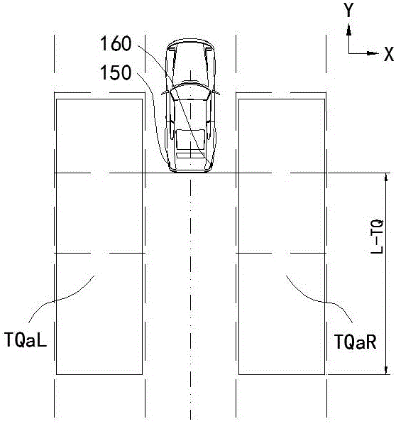
technical field [0001] The invention belongs to the field of automobile electronic equipment, and in particular relates to an automobile blind spot detection system and detection method comprising a single microwave radar sensor and several ultrasonic sensors. Background technique [0002] The current vehicle blind spot detection system, also known as blind spot monitoring system, blind spot assist system, etc., most models use vehicle-mounted microwave radar sensors. The target object (usually refers to the vehicle) within the blind area of ​​the exterior rearview mirror of the adjacent lane on the left and right sides of the vehicle is detected. [0003] figure 1 It is the original detection schematic diagram of the microwave radar blind zone detection system. Take the left probing description as an example (the right is symmetrical to the left). The microwave radar sensor 150 is arranged on the left side of the rear bumper of the car (referred to as the rear bumper), a...

Claims


Application Information

Patent Timeline
Patent Type & Authority Applications(China)
IPC IPC(8): G01S13/93G01S15/93
CPCG01S13/931G01S15/931G01S2013/9324G01S2013/9315G01S2013/93274G01S2013/93272G01S15/93G01S13/93
Inventor 陈武强
Owner XIAMEN AUTOSTAR ELECTRONICS CO LTD
Learn More