
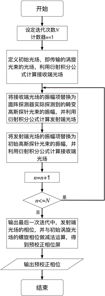
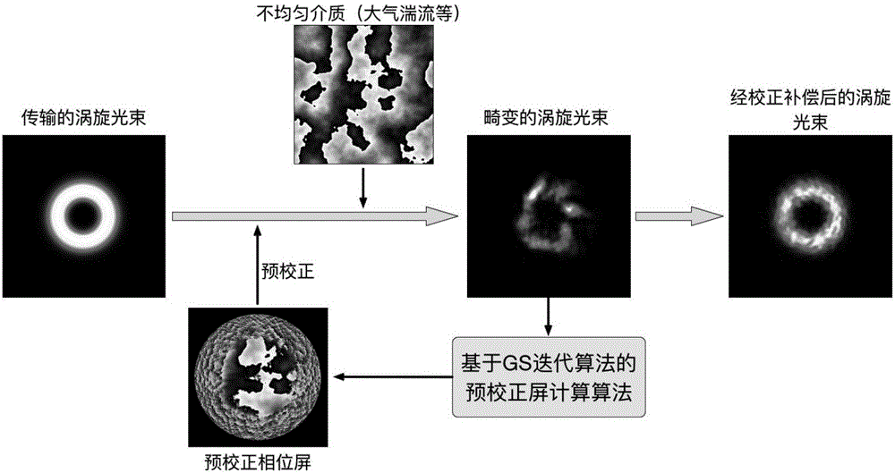
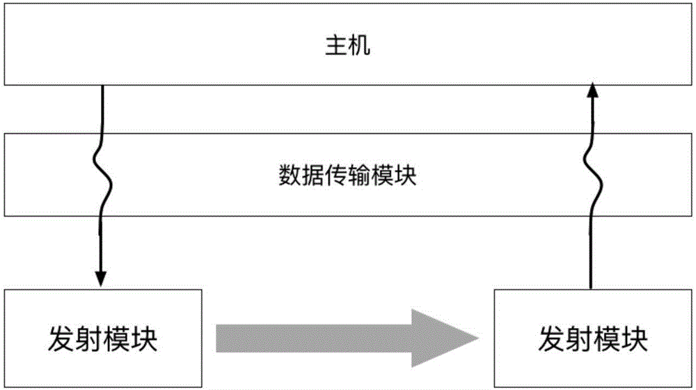
Self-adaptive correction method and system of wavefront-free and probe-free distortion vortex light beam

An adaptive pre-correction and vortex beam technology, applied in the field of optoelectronics, can solve problems such as increasing system complexity, and achieve the effects of real-time pre-correction, simple operation, and reduced system cost

Active Publication Date: 2017-01-25
BEIJING INSTITUTE OF TECHNOLOGYGY
View PDF5 Cites 9 Cited by
  • Summary
  • Abstract
  • Description
  • Claims
  • Application Information

AI Technical Summary

Problems solved by technology

However, the above-mentioned existing adaptive correction technologies for distortion vortex beams all need to use Gaussian probe beams, which increases the complexity of the system to a certain extent

Method used


Image

  • Self-adaptive correction method and system of wavefront-free and probe-free distortion vortex light beam
  • Self-adaptive correction method and system of wavefront-free and probe-free distortion vortex light beam
  • Self-adaptive correction method and system of wavefront-free and probe-free distortion vortex light beam

Examples


Embodiment 1

[0056] Example 1: Adaptive pre-correction of vortex beams

[0057] In this embodiment and the following several embodiments, the power spectrum inversion method is used to simulate atmospheric turbulence. In particular, two different intensities of atmospheric turbulence are simulated, and the Fried coefficient r 0 1mm and 3mm respectively. This in turn introduces phase distortion. This embodiment adopts +1 order, +2 order, +3 order, +4 order, +5 order and +6 order vortex beam incidence, such as Figure 7 shown. Figure 7 Among them, from top to bottom are no turbulent flow and turbulent flow (r 0 = 1mm) without correction, with turbulence (r 0 = 1mm) with correction, with turbulent flow (r 0 = 3mm) without correction, with turbulence (r 0 =3mm) measured light intensity distribution of vortex beams; from left to right are +1~+6 order vortex beams respectively. From Figure 7 It can be seen that the light intensity distribution is improved well before and after pre-cali...

Embodiment 2

[0060] Example 2: Changes in model purity with the number of iterations in the host after pre-calibration

[0061] In the present invention, the host computer calculates the number of iterations of the pre-correction phase screen, which will affect the effect of the pre-correction. In this example, we measure the +2nd-order vortex beam passing through r 0 =1mm(D / r 0 =3.46) and r 0 =3mm(D / r 0 =1.15), the model purity after pre-correction of different iterations, such as Figure 10 As shown, it can be seen that the more iterations, the higher the purity of the model.

[0062] In summary, it can be concluded that the self-adaptive pre-correction method and system for a distorted vortex beam without a wavefront probe of the present invention can well compensate the phase distortion of the vortex beam caused by the uneven refractive index of the medium. The invention can quickly complete the adaptive pre-correction of the vortex beam in real time, and can also change the effec...


PUM


Abstract

The invention discloses a self-adaptive correction method and a self-adaptive correction system of a wavefront-free and probe-free distortion vortex light beam. The method and the system can be applied to correct and compensate the phase distortion of a vortex light beam during the transmission process for uneven refractive index of a medium. The light intensity distribution of the distortion vortex light beam is directly read through an area array detector in a receiving module, and a pre-correction phase screen can be obtained by combining with a phase recovery algorithm based on GS iterative algorithm, and a pre-correction phase screen can be obtained. The pre-correction phase screen is acted in a vortex light beam emitted by an emitting module, thus the self-adaptive pre-correction of the vortex light beam is realized, and the phase distortion is further compensated. The experiment shows that the self-adaptive pre-correction system can reduce the crosstalk between models, and largely promote the model purity degree. The system is stable in structure and can realize the real-time correction of the phase distortion. Besides, the invention has not applied a probe method and an experiment wavefront analyzer, the system complexity is reduced and cost is saved.

Description

technical field [0001] The invention relates to the field of optoelectronic technology, in particular to a method and system for adaptive correction of distorted vortex beams without wavefronts and probes Background technique [0002] The vortex beam is a new type of laser beam with a spiral wavefront structure and carries orbital angular momentum. Compared with the Gaussian beam, the cross-sectional light intensity of the vortex beam is a hollow ring, which is caused by the phase singularity in the center of the beam of its helical phase. As early as 1992, Allen et al. have found that the complex amplitude expression of the vortex beam contains term, where l is the angular quantum number, also known as the topological charge number, is the angular coordinate (L. Allen et al., Physical Review A, Vol. 45, 1992, p. 8185). Each photon in the vortex beam carries Orbital angular momentum ( is the reduced Planck constant), that is, the angular quantum number l determines ...

Claims


Application Information

Patent Timeline
Patent Type & Authority Applications(China)
IPC IPC(8): G01J9/00
CPCG01J9/00
Inventor 高春清付时尧王彤璐张世坤
Owner BEIJING INSTITUTE OF TECHNOLOGYGY
Learn More