
Connector applied to oil circuit transmission in motor vehicle

A connector and motor vehicle technology, applied in the direction of couplings, mechanical equipment, etc., can solve the problems of difficult loading and unloading, insufficient retention force of locking fasteners, and inconvenient installation, so as to improve the efficiency of installation/disassembly and ensure sealing. and stability, avoiding the effect of installation time

Active Publication Date: 2017-01-25
大厂回族自治县东进自动化设备有限公司
View PDF5 Cites 2 Cited by
  • Summary
  • Abstract
  • Description
  • Claims
  • Application Information

AI Technical Summary

Problems solved by technology

[0002] A connector is a device used to transport fluids such as gas and liquid. Usually, the connector is connected by pipes, pipe connectors, valves, etc.; The connection methods of the existing joints include threaded connection, welding and pressing, etc. In the actual operation and installation, there are some problems, such as joint manufacturing, inconvenient installation, difficult loading and unloading, slow installation speed, locking Insufficient retaining force of fasteners and other problems, in order to solve these problems, quick connectors came into being
[0003] In the current existing connectors, all the locking fasteners are submerged into the quick connector such as the female joint, and a considerable part of the locking fasteners have insufficient holding force on the male joint to ensure the reliable connection of the pipeline.
At the same time, after multiple disassembly and assembly, the locking fastener is easy to lose its original holding force, so the connection will be disconnected

Method used


Image

  • Connector applied to oil circuit transmission in motor vehicle
  • Connector applied to oil circuit transmission in motor vehicle
  • Connector applied to oil circuit transmission in motor vehicle

Examples


Embodiment Construction

[0023] The technical scheme of the present invention will be further described below in conjunction with the accompanying drawings of the description:

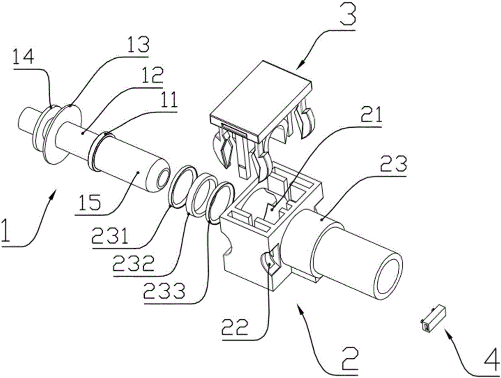
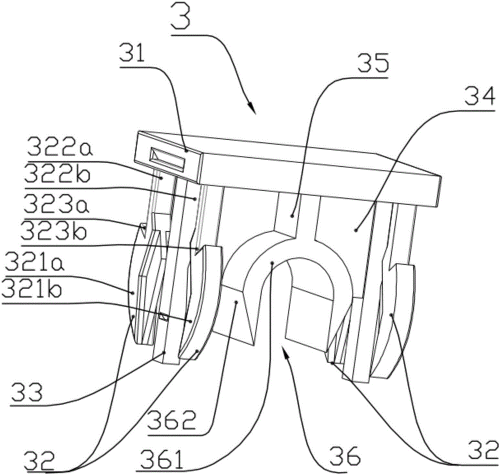
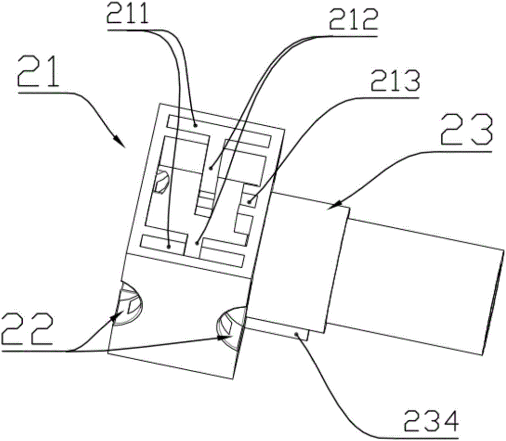
[0024] Such as Figure 1-8 As shown, the present invention provides a connector applied to oil circuit transmission in motor vehicles, specifically: as figure 1 and Figure 6-8 As shown, the connector includes a male connector 1 and a female connector 2, the male connector 1 is fixedly connected to the female connector 2 through a locking fastener 3; the male connector 1 is a hollow conduit, and the male connector 1 is sequentially made of The connecting pipe 15, the first annular protrusion 11, the second annular protrusion 13, the third annular protrusion 14 and the first hose connection part are integrally connected; between the first annular protrusion 11 and the second annular protrusion 13 to form a snap-fit ​​groove 12 that can cooperate with the locking fastener 3;

[0025] Such as figure 1 , image 3 and Figure...


PUM


Abstract

The invention provides a connector applied to oil circuit transmission in a motor vehicle. The connector comprises a male joint and a female joint, wherein the male joint is fixedly connected with the female joint through a locking fastener; the male joint is a hollow conduit; the male joint is formed by integrally connecting a male connecting tube, a first annular bump, a second annular bump, a third annular bump and a first hose connecting part in sequence; a clamping groove which can be matched with the locking fastener is formed between the first annular bump and the second annular bump. In the connector, the locking fastener designed with a symmetric structure is adopted, so that mounting time consumed by adjustment of an existing self-locking device or the locking fastener in a forward direction and a backward direction is saved, namely, the cost is lowered, the assembling / disassembling efficiency is increased, and the performance of the locking fastener is ensured; meanwhile, the locking fastener is applied to the connector applied to the oil circuit transmission in the motor vehicle, so that the airtightness and stability of the connector applied to the oil circuit transmission in the motor vehicle are ensured.

Description

technical field [0001] The invention belongs to the technical field of motor vehicle pipeline / pipeline connection, and in particular relates to a connector applied to oil circuit transmission in a motor vehicle. Background technique [0002] A connector is a device used to transport fluids such as gas and liquid. Usually, the connector is connected by pipes, pipe connectors, valves, etc.; The connection methods of the existing joints include threaded connection, welding and pressing, etc. In the actual operation and installation, there are some problems, such as joint manufacturing, inconvenient installation, difficult loading and unloading, slow installation speed, locking In order to solve problems such as insufficient fastener holding force, quick connectors came into being. [0003] In the current existing connectors, all locking fasteners are submerged into quick connectors such as female joints, and a considerable part of the locking fasteners have insufficient holdin...

Claims


Application Information

Patent Timeline
Patent Type & Authority Applications(China)
IPC IPC(8): F16L37/12
CPCF16L37/1225
Inventor 黄松檀
Owner 大厂回族自治县东进自动化设备有限公司
Learn More