Dismountable high-intensity pull riveting pin and connecting and dismounting method

A rivet pin, high-strength technology, applied in the direction of connecting components, rivets, threaded fasteners, etc., can solve the problems of inability to disassemble and reuse, poor clamping of the jaws, and easy blockage of the pull grooves, and achieves fast tightening. Strengthen the force, solve the stress concentration and stuck, reduce the effect of the head breaking and falling off

Active Publication Date: 2017-01-25
MEISHAN CRRC FASTENING SYST CO LTD
View PDF6 Cites 7 Cited by
  • Summary
  • Abstract
  • Description
  • Claims
  • Application Information

AI Technical Summary

Problems solved by technology

[0011] The purpose of the detachable high-strength riveting pin and its connection and disassembly method proposed by the present invention is to solve the problems of high positioning requirements, easy blockage of the pull groove, easy jamming, concentrated stress, and poor clamping degree of the claws in the existing riveting pin riveting. Problems such as poor strength, inability to disassemble and reuse

Method used


Image

  • Dismountable high-intensity pull riveting pin and connecting and dismounting method
  • Dismountable high-intensity pull riveting pin and connecting and dismounting method
  • Dismountable high-intensity pull riveting pin and connecting and dismounting method

Examples


Embodiment Construction

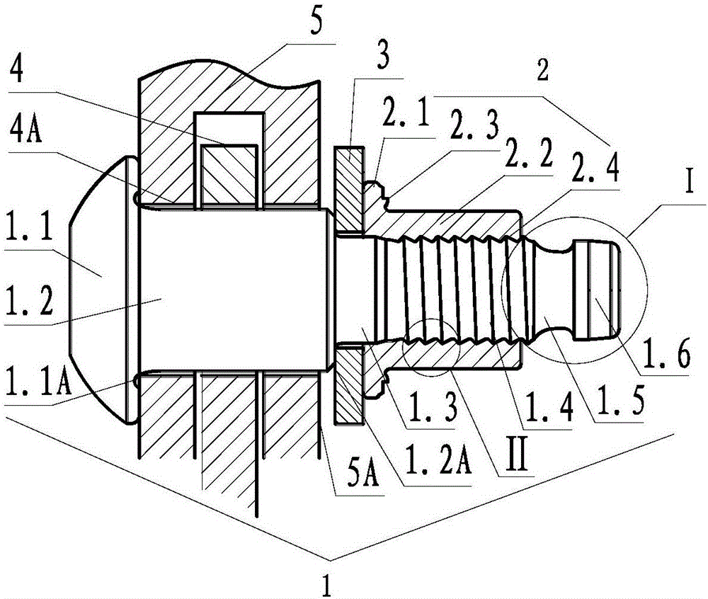
[0043] See figure 1, In this embodiment, the detachable high-strength blind riveting pin is composed of a pin shaft 1, a collar 2 and a washer 3. The pin shaft 1 includes a riser 1.1, a pin post 1.2, a short polished rod 1.3, a locking groove section 1.4 and a tail connected in sequence from the front end to the rear end. The pin 1.2 is tightly matched with the pin hole 4A of the rotating part 4 and the horseshoe-shaped part 5 of the connected part. The collar 2 is tightly sleeved on the locking groove section 1.4. Washer 3 is sleeved on the outside of short polished rod 1.3. The collar 2 includes a flange 2.1 and a straight cylinder 2.2 from the front end to the rear end, the rear end surface of the flange has a convex point 2.3, and the rear end of the inner hole of the straight cylinder has a locking tooth 2.4. New design of the present invention has:

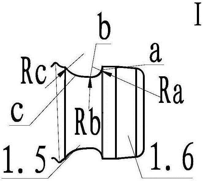
[0044] 1) see figure 1 , figure 2 , the tail is a single-groove short tail composed of a continuous smooth arc su...


PUM


Abstract

The invention relates to a dismountable high-intensity pull riveting pin and a connecting and dismounting method. The pull riveting pin consists of a cap, a pin post, a short polished rod, a locking groove section, a tail pin shaft, a sleeve ring and a gasket. The single-groove short tail with a continuous smooth arc surface pull groove is designed; the manufacturing is easy; the cost is low; the installation is convenient; three sections of circular arc surfaces with different radii are used. The problems of riveting stress concentration and clamping of the tail are solved. During the riveting, the end surface is positioned; the clamp claw is automatically engaged to the optimum position; the locking groove section thread type is a curve combining a circular arc with a straight line; the fastening force is greatly enhanced. A dismounting groove is formed in the root part of the cap, so that the cap fracturing and falling due to root part stress concentration are effectively prevented. The depth of a hardening layer on the surface of the pin post is 2 to 6mm; the surface hardness and the wear resistance are effectively improved; the service life is prolonged. The pin shaft short tail which cannot be broken through pulling and the high-intensity pin post are used for realizing the sleeve ring cutting of a cutting device; the dismounting is convenient; the repeated use of the pin shaft is convenient; the utilization rate is improved; the use and maintenance cost is reduced; the dismountable high-intensity pull riveting pin is used for the connection and the dismounting in positions of antitheft locks of hinging structures, horseshoe-shaped hinging pulleys on a train and the like.

Description

[0001] (1) Technical field: The invention relates to a detachable high-strength blind riveting pin and a connection and disassembly method, which relate to cold drawing riveting and cutting technology. It is mainly used for the connection of anti-loose and anti-theft components that bear shear force. It belongs to riveting (B21J) and fasteners (F16B) of metal machining. [0002] (two) background technology: [0003] See Figure 10 , An existing riveting pin N consists of a pin shaft 1n, a collar 2n and a washer 3n. Pin shaft 1n is made up of cap head 1.1n, pin post 1.2n, short polished rod 1.3n, locking groove section 1.4n and afterbody (another kind of blind riveting pin also can not have washer and cap head.). The locking groove section is used for locking with the collar after riveting. The tail is used for cooperating with the claws at the front end of the riveter to catch the pin shaft when riveting. After the connection, the pin shaft, the washer and the collar will be...

Claims


Application Information

Patent Timeline
Patent Type & Authority Applications(China)
IPC IPC(8): F16B19/10B21J15/02
CPCB21J15/02F16B19/1027
Inventor 代广成刘宇李新荣贾云龙王霞何旭张雄
Owner MEISHAN CRRC FASTENING SYST CO LTD
Why Eureka
Try Eureka