An Early Stiffness Adjustable Coil Spring Damper

A coil spring and damper technology, applied in the field of shock absorbers, can solve the problems of reducing shock absorption costs, waste of resources, unable to change the early stiffness of dampers, etc., and achieve the effects of reducing shock isolation costs and shortening length

Active Publication Date: 2020-11-10
ANHUI XINZE TECH CO LTD
View PDF3 Cites 0 Cited by
  • Summary
  • Abstract
  • Description
  • Claims
  • Application Information

AI Technical Summary

Problems solved by technology

However, this utility model patent obviously has the following disadvantages: 1. Two coil springs are required, and the length of the entire damper is relatively long, which is not suitable for installation in a space with a small distance; 2. It is difficult or even impossible to ensure the two springs in the process Only the stiffness of the spring (including tensile stiffness and compression stiffness) is equal, so the shock absorption effect is different in different wind directions; 3. The early stiffness of the damper cannot be changed to achieve the preset wind resistance level and reduce the cost of shock absorption; 4. A helical spring works in two states of tension and compression at the same time. The metal material and production process of the existing spring are difficult to meet the requirements. The two working states of tension and compression can only be realized by reducing the elastic deformation range of the helical spring. , which obviously wastes resources
It can be seen that although the stiffness of the spring in the patent application scheme can be changed, the effective working length of the spring is not only significantly shortened, but also can only be compressed for energy consumption and vibration reduction, and cannot be stretched for energy consumption and vibration reduction.
In addition, the stiffness of the spring is changed by changing the effective working length of the spring. The adjustment range is limited by the material and shape of the spring itself.

Method used


Image

  • An Early Stiffness Adjustable Coil Spring Damper
  • An Early Stiffness Adjustable Coil Spring Damper
  • An Early Stiffness Adjustable Coil Spring Damper

Examples


example 1

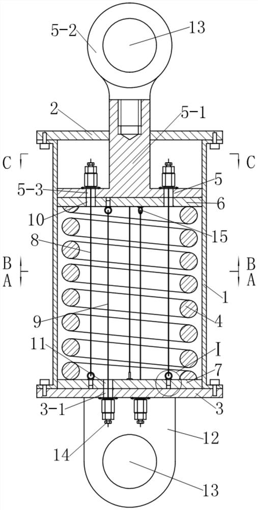
[0034] see figure 1 , the early coil spring damper with adjustable stiffness in this example is an energy-dissipating device that can be used for seismic reinforcement of building structures. It includes a guide sleeve 1, a first end cover 2 and a second The end cap 3, wherein, the first end cap 2 and the second end cap 3 are respectively fixedly connected to the two ends of the guide sleeve by screws. A cylindrical helical compression spring 4 is arranged axially in the guide sleeve 1, and a driving member extends from the center of the first end cover 2 into the guide sleeve 1 and presses on the cylindrical helical compression spring 4, Wherein, the driving member is composed of a dynamic pressure plate 5 located at the upper end of the cylindrical helical compression spring 4 and movably matched with the guide sleeve 1, and a driving rod 5-1 extending upward from the upper surface of the dynamic pressure plate 5 out of the guide sleeve 1. The end of the driving rod 5-1 lo...

example 2

[0049] see Figures 12 to 16 , the early coil spring damper with adjustable stiffness in this example is a kind of vibration isolation device (also called isolation support) that can be used for vertical isolation of buildings. Compared with Example 1, this example mainly has the following differences:

[0050] 1. As a vibration-isolation support, in order to facilitate installation, in this example, the connecting ear plate provided on the second end cover 3 in Example 1 is omitted, and the second end cover 3 is extended axially downward from the edge and then to the It extends radially outward, and is evenly provided with connecting bolt holes 16 at the edge. The second end cover 3 is used as the base of the shock-isolation support, and the length of the downward axial extension needs to be greater than the self-locking tensioning anchor With a height of 14. The driving rod 5-1 of the driving member is a metal tube that extends from the upper surface of the automatic pressu...

example 3

[0054] see Figures 17-21 , compared with Example 2, this example has the following main differences:

[0055] The first group of preloaded steel cables 8 and the second group of preloaded steel cables 9 are respectively composed of five preloaded steel cables, and the number of the steel cable self-locking tensioning anchors 14 is ten.

[0056] Other implementations of this example other than the above are the same as Example 2.


PUM


Abstract

The invention discloses a spiral spring damper with adjustable early-period rigidity. The spiral spring damper is characterized in that a reverse pressure device is also arranged in a guide sleeve; the reverse pressure device comprises two groups of (at least three) prepressing steel cables and two floating press plates, wherein the two groups of prepressing steel cables are symmetrically distributed in a center hole of a cylindrical spiral compression spring in a linear state by surrounding the axial line of the guide sleeve; one end of one group of prepressing steel cables is fixed on the floating press plate adjacent to a driving component; the other end of the one group of prepressing steel cables penetrates through the floating press plate adjacent to a second end cover and is anchored on the second end cover through a steel rope self-locking tensioning anchor; one end of the other group of prepressing steel cables is fixed on the floating press plate adjacent to the second end cover; the other end of the other group of prepressing steel cables penetrates the floating press plate adjacent to the driving component and is anchored on the driving component by the steel rope self-locking tensioning anchor; the two groups of prepressing steel cables are tensioned, so that the cylindrical spiral compression spring is always clamped between the two floating press plates.

Description

technical field [0001] The present invention relates to shock absorbing devices, and more particularly to dampers employing helical compression springs. Background technique [0002] A damper is a shock-absorbing device that consumes motion energy by providing motion resistance. The use of dampers for energy dissipation and shock absorption is a traditional technology widely used in industries such as aerospace, aviation, military industry, guns, and automobiles. Since the 1970s, people have gradually applied the technology of using dampers to consume energy and reduce shocks to structural engineering such as buildings, bridges, and railways. The coil spring damper is widely used in the anti-seismic structures of various buildings because of its high impact resistance, low cost and good shock absorption effect. [0003] People pursue a comprehensive anti-seismic performance combining "resistance" and "loss" for the design of buildings, especially the anti-seismic structure...

Claims


Application Information

Patent Timeline
Patent Type & Authority Patents(China)
IPC IPC(8): E04B1/98E04H9/02E02D31/08
CPCE02D31/08E04H9/021
Inventor 沈珊胡济福胡济全
Owner ANHUI XINZE TECH CO LTD
Why Eureka
Try Eureka