
A motor-driven continuous cycle elevator system

An elevator system and motor-driven technology, applied in the mechanical field, can solve the problems of fading, limited transportation capacity, large horizontal space, etc., and achieve the effect of large transportation volume

Active Publication Date: 2019-07-23
南宁邃丛赋语科技开发有限责任公司
View PDF7 Cites 0 Cited by
  • Summary
  • Abstract
  • Description
  • Claims
  • Application Information

AI Technical Summary

Problems solved by technology

[0003] However, for the deficiencies of vertical elevators, firstly, the car lifts up and down in the vertical shaft. If the safety system breaks down, it will easily cause the car to fall from a tall building, causing casualties; Only one car is running. For example, when waiting on the first floor, it is necessary to wait for the elevator car to complete the upward transportation task first, and then descend to carry out the second upward transportation task. The waiting time is long, and the ability to arrive at any time cannot be achieved.
The shortcomings of the escalator are that it is not suitable for large-distance transportation in the vertical direction. When the height is too large, the horizontal space required for the inclined installation of the escalator is large. Secondly, if the large-distance transportation is carried out, the open escalator is safe. Poor performance, if you accidentally fall, it will fall for a long distance and it will be difficult to rescue. Moreover, one pedal of the escalator can only stand two people, and the transportation capacity is limited

Method used


Image

  • A motor-driven continuous cycle elevator system
  • A motor-driven continuous cycle elevator system
  • A motor-driven continuous cycle elevator system

Examples


Embodiment 1

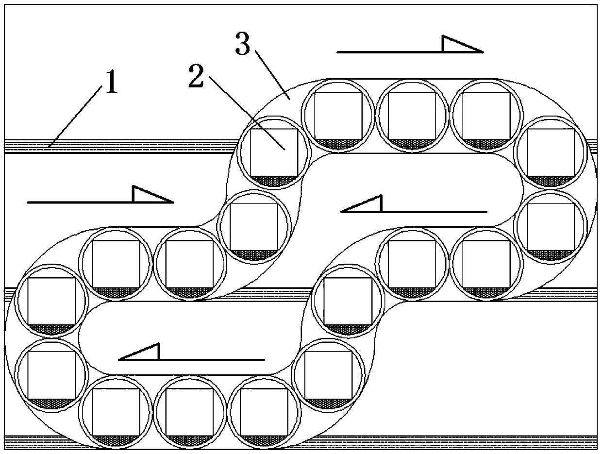
[0030] A motor-driven continuous circulation elevator system comprising a shaft 3 and a car 2,

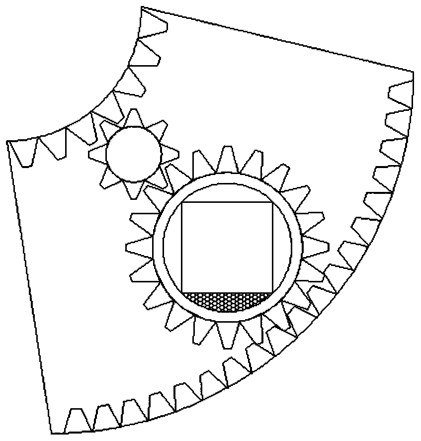
[0031] Described shaft 3 comprises horizontal shaft 23, vertical shaft 21 and arc shaft 22, and horizontal shaft 23 is arranged on the floor of floor, and vertical shaft 21 is arranged between floors, and between horizontal shaft 23 and vertical shaft 21 Connected by arc shaft 22,

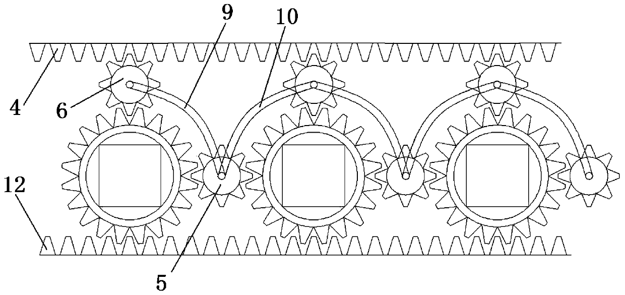
[0032] Two top surface rack tracks 4 are installed on the top surface of the horizontal shaft 23 and are continuously laid along the shaft including all the horizontal shafts 23, arc shafts 22 and vertical shafts 21 to form a closed circle; the two bottom rack tracks 12 Installed on the bottom surface of the horizontal shaft 23 and continuously laid along the shaft including all the horizontal shaft 23, the arc shaft 22 and the vertical shaft 21 to form a closed circle;

[0033] Described car 2 comprises cylinder liner 15, first travel bearing 14, second travel bearing 13, first transition gear 18, sec...


PUM


Abstract

The invention relates to a motor-driven continuous circulating elevator system. The motor-driven continuous circulating elevator system comprises a hoistway and a car, wherein two top gear rack tracks and two bottom gear rack tracks are arranged in the hoistway; inner circles of a first walking bearing and a second walking bearing of the car are fixedly arranged on a cylindrical inner container, outer circles of the first walking bearing and the second walking bearing are outer toothed rings, the lower end of the outer toothed ring of the first walking bearing is engaged with one bottom gear rack track, the upper end of the outer toothed ring of the first walking bearing is engaged with the lower end of a first transition gear, the engaged upper end of the first transition gear is engaged with one top gear rack track, one side of a second transition gear is engaged with the outer toothed ring of the first walking bearing, and the other side of the second transition gear is engaged with an outer toothed ring of a first walking bearing of the other car. The motor-driven continuous circulating elevator system has the advantages that the absolute safety is realized, the required space is small, the ascending in the vertical direction is realized by one circular arc-shaped curve, the carrying amount is large, multiple passengers can be carried in one car, and the safety, rapidity and comfortability effects are realized.

Description

technical field [0001] The invention relates to the mechanical field, in particular to a motor-driven continuous cycle elevator system. Background technique [0002] Elevator refers to the permanent transportation equipment that serves several specific floors in the building, and its car runs on at least two rigid rails that are perpendicular to the horizontal plane or less than 15° from the vertical. There is also a step type, and the tread plate is installed on the crawler belt to run continuously, commonly known as an escalator or a moving walk. Fixed lifting equipment serving specified floors. A vertical elevator has a car running between at least two vertical or inclination angles of less than 15° rigid guide rails. The size and structure of the car are convenient for passengers to enter and exit or to load and unload goods. It is customary to use elevator as a general term for vertical transportation in buildings regardless of its driving mode. [0003] However, fo...

Claims


Application Information

Patent Timeline
Patent Type & Authority Patents(China)
IPC IPC(8): B66B9/02B66B9/10B66B11/04
CPCB66B9/022B66B9/10B66B11/005B66B11/0461B66B2009/006
Inventor 覃陈祚
Owner 南宁邃丛赋语科技开发有限责任公司
Learn More