
A ring two-way toggle arrangement and grinding step equipment

An automatic arrangement and step technology, applied in grinding/polishing equipment, metal processing equipment, grinding machines, etc., can solve the problems of high labor cost, complex structure, poor arrangement effect, etc. simple effect

Inactive Publication Date: 2018-10-30
FOSHAN SHUNDE JINHAITIAN MACHINERY CO LTD
View PDF1 Cites 0 Cited by
  • Summary
  • Abstract
  • Description
  • Claims
  • Application Information

AI Technical Summary

Problems solved by technology

[0004] One of the purposes of the present invention is to address the deficiencies of the prior art, and overcome the inability to realize automatic alignment before the piston rings are polished in the prior art, which consumes high manpower costs, and some automatic alignment devices have complex structures and poor alignment effects, and thus cannot be realized. The batch grinding of piston ring openings and the problem that the grinding steps of piston ring openings cannot be automated and highly efficient

Method used


Image

  • A ring two-way toggle arrangement and grinding step equipment
  • A ring two-way toggle arrangement and grinding step equipment
  • A ring two-way toggle arrangement and grinding step equipment

Examples


Embodiment

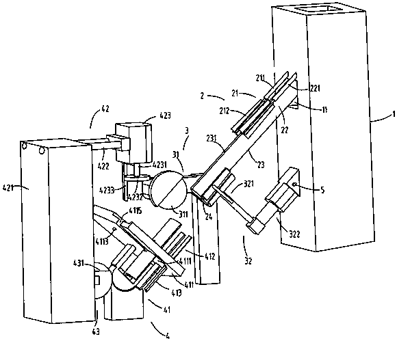
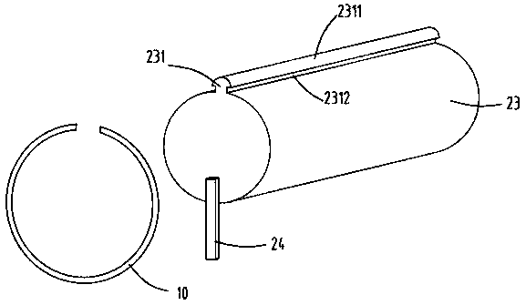
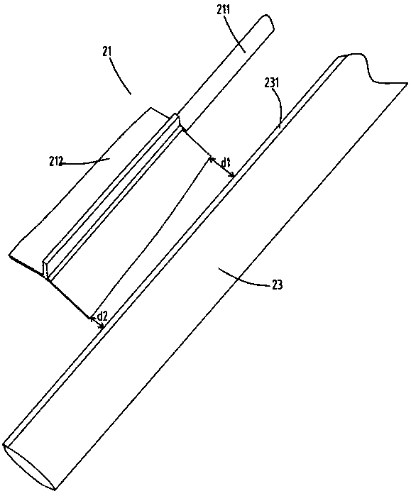
[0032] figure 1 It is a schematic diagram of the structure of the ring two-way toggle arrangement and the grinding step equipment, figure 2 A schematic diagram of the rod structure, image 3 It is a schematic diagram of the structure of the automatic arrangement device, Figure 4 A cross-sectional schematic diagram of the automatic arrangement device, Figure 5 It is a schematic diagram of the structure of the open grinding step part, Figure 6 It is a schematic diagram of the structure of the fixed plate and the turning device, Figure 7 It is a schematic diagram of the processed piston ring structure. Such as figure 1 , figure 2 , image 3 , Figure 4 , Figure 5 , Figure 6 and Figure 7 As shown, a ring bidirectional toggle arrangement and grinding step equipment, including a breaching machine 1, an automatic arrangement device 2, an opening grinding device 3 and an opening grinding step part 4; The material outlet 11 is used to neatly arrange the piston rings ...


PUM


Abstract

The invention relates to two-way shifting, arranging and step-polishing equipment for processing of piston rings. The equipment comprises a splitting machine, an automatic arranging device, a split polishing device and a split step polishing unit. The automatic arranging device is arranged at the position of a discharge outlet of the splitting machine and used for arranging the split piston rings linearly according to positions of splits of the piston rings. The split polishing device is arranged at the back end of the automatic arranging device and used for polishing the splits of the piston rings. The split step polishing unit is arranged at the back end of the split polishing device and used for polishing steps of the splits of the piston rings. The automatic arranging device comprises a rotary shifting brush a and a rotary shifting brush b which are arranged on the splitting machine, a feed rod extending outwards from the discharge outlet of the splitting machine and a stop piece at the tail end of the feed rod. The two-way shifting, arranging and step-polishing equipment overcomes defects that, in the prior art, automatic arrangement of the piston rings cannot be realized before polishing, cost for manpower is high, and some conventional automatic arranging devices are of complex structure and poor arranging effect, which is not good for realizing split polishing of the piston rings in batch, and incapable of achieving automation and high efficiency of step polishing of the splits of the piston rings.

Description

technical field [0001] The invention relates to the technical field of piston ring production equipment, in particular to a ring bidirectional toggle arrangement and grinding step equipment. Background technique [0002] In the production process of piston rings, there are two processes of breaking the ring and then grinding the break. Some piston rings also need to grind steps on the front and back sides of the opening of the piston ring. The two steps cooperate to increase the piston ring. In the prior art, the rings are usually broken on the breaking machine, and then the workers take the broken piston rings to polish, and some manually polish them one by one. The quality of the polished piston rings is better but the efficiency is low. , the labor cost is high, and after polishing, the rings are installed one by one on the manual mold to grind the steps. Since the steps are one positive and one reverse, a single piston ring needs to be loaded and unloaded twice to grind ...

Claims


Application Information

Patent Timeline
Patent Type & Authority Patents(China)
IPC IPC(8): B65G47/26B65G47/74B24B9/00B24B41/00B24B41/06
CPCB24B9/005B24B41/00B24B41/005B24B41/06B65G47/26B65G47/74B65G2201/0214
Inventor 丁震华
Owner FOSHAN SHUNDE JINHAITIAN MACHINERY CO LTD
Learn More