Pantograph

A pantograph and bow head technology, applied in the field of pantographs, can solve the problems of large wind resistance, large force of spring boxes and other components, and short fatigue life, so as to reduce air lift force, improve flow stability, and improve The effect of fatigue life

Active Publication Date: 2017-01-25
ZHUZHOU ELECTRIC LOCOMOTIVE CO LTD
View PDF5 Cites 22 Cited by
  • Summary
  • Abstract
  • Description
  • Claims
  • Application Information

AI Technical Summary

Problems solved by technology

Due to the structural arrangement, it is necessary to ensure that the bow head shaft is connected to the spring box, which will cause the connection point between the bow head shaft and the upper arm to be far away from the slide plate, resulting in a large bow head torque for keeping the bow head vertical , the balance bar is stressed and the fatigue life is short
[0008] Moreover, the larger distance makes the lifting force of the air on the skateboard larger, resulting in a large force on the spring box and other components, which is easy to damage the spring box and other components
[0009] 2. When subjected to a major impact, the connecting pin shaft at the joint between the upper arm and the bow head is easily broken and the bow head falls, which seriously affects the safety of other vehicle equipment and the safety of the vehicle's surroundings
The inclined balance bar 16 is subject to greater wind resistance, which is not conducive to the aerodynamic performance of the pantograph when receiving current, especially on high-speed EMUs, which has a greater impact on the stability of receiving current

Method used


Image

  • Pantograph
  • Pantograph
  • Pantograph

Examples


Embodiment Construction

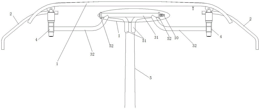
[0049] Such as Figure 1-8 As shown, a pantograph includes a chassis 6, a lower arm 7 mounted on the chassis 6, an upper arm 5 hinged to the lower arm 7, one end hinged to the lower end of the upper arm 5 and the other end to the chassis 6Hinged pull rod 9, lifting bow driving device, and bow head 17, said bow head 17 includes bow angle 2, bow head rotating shaft 3, elastic buffer devices connected to both ends of bow head rotating shaft 3, two ends across bow head rotating shaft 3 The elastic buffer device at the end and the slide plate 1 fixedly connected with the elastic buffer device. The elastic buffer device is preferably a spring box 4 . The spring box 4 is provided with a bow horn mounting plate, and the bow horn 2 is mounted on the bow horn mounting plate. The upper end of the upper arm 5 is extended with a connecting portion 12 , and the connecting portion 12 is hinged to the bow head rotating shaft 3 .

[0050] The distance between the connecting position of the ...


PUM


Abstract

The invention discloses a pantograph which comprises an underframe, a lower arm rod, an upper arm rod, a pull rod, a lifting pantograph driving device and a pantograph head. The pantograph head comprises a pantograph corner, a pantograph head rotating shaft, an elastic buffer device and a sliding plate. A connecting part extends and is arranged at the upper end of the upper arm rod and hinged to the pantograph head rotating shaft, and the length between the joint of the pantograph head rotating shaft and the connecting part is smaller than the length between the joint of the pantograph head rotating shaft and the elastic buffer device and the sliding plate is smaller than the length between the joint of the pantograph head rotating shaft and the elastic buffer device and the sliding plate. The pantograph further comprises a balance rod system, the balance rod system comprises a first rod hinged to the upper end of the lower arm rod, a second rod hinged to the upper end of the upper arm rod, a fourth rod hinged to the pantograph head rotating shaft and a third rod, wherein one end of the third rod is hinged to the free end of the second rod, and the other end of the third rod is hinged to the free end of the fourth rod. The other end of the first rod is hinged to the middle of the second rod. The pantograph can reduce stress of the balance rod system and air lift force of the sliding plate, improve fatigue life of a structure member and have the advantages of being high in current collection stability and small in wind resistance.

Description

technical field [0001] The invention belongs to rail vehicle equipment, in particular to a pantograph. Background technique [0002] A single-arm pantograph generally consists of an underframe, a lower arm, an upper arm, a tie rod, a balance bar, and a bow head. The balance bar plays the role of balance and support, so that the angle between the bow head and the horizontal plane remains unchanged during the bow raising process. [0003] When the pantograph is raised and in contact with the network cable to receive current, due to the high running speed of the vehicle, the upper arm, lower arm, pull rod, balance bar, etc. of the pantograph will be subject to greater wind resistance, which will affect The stability of the nominal contact pressure between the Pantograph and Catenary leads to unstable flow. Therefore, when designing and manufacturing pantographs, it is hoped that the bow head can be kept stable. [0004] The pantograph bow head plays a decisive role in the cu...

Claims


Application Information

Patent Timeline
Patent Type & Authority Applications(China)
IPC IPC(8): B60L5/20B60L5/22
CPCB60L5/20B60L5/22B60L5/26B60L5/28
Inventor 陈明国杨瀛瑜张彦林陈珍宝陈敏坚冯叶孙云嵩李军孙宁周维曹秀峰王秋红
Owner ZHUZHOU ELECTRIC LOCOMOTIVE CO LTD
Why Eureka
Try Eureka