Novel volute centrifugal fan provided with permanent-magnet brushless motor system

A technology of permanent magnet brushless motor and centrifugal fan, applied in the direction of machine/engine, casing/cover/support, electromechanical device, etc., can solve the problems of shortened life, low heat dissipation efficiency, increased trouble, etc., to prolong the service life , the effect of speeding up heat dissipation and improving operating efficiency

Active Publication Date: 2017-01-18
ZHE JIANG YILIDA VENTILATOR CO LTD
View PDF7 Cites 9 Cited by
  • Summary
  • Abstract
  • Description
  • Claims
  • Application Information

AI Technical Summary

Problems solved by technology

In this way, the motor body of the permanent magnet brushless motor system is the smallest, but the driver is added. If the driver and the permanent magnet motor body are integrated, the overall volume of the permanent magnet brushless motor system will also increase, which directly affects the performance of the volute centrifugal fan. The size of the permanent magnet brushless motor system generally separates the driver and installs it on the outer surface of the volute fan, but this solution will affect the overall size of the fan, affect the customer's installation and use, and increase the trouble of installation. At the same time, the separated The drive also dissipates heat through natural heat dissipation. This heat dissipation method with low heat dissipation efficiency will reduce the operating efficiency and life of the drive, and reduce the overall efficiency and life of the volute centrifugal fan with a permanent magnet brushless motor system.

Method used


Image

  • Novel volute centrifugal fan provided with permanent-magnet brushless motor system
  • Novel volute centrifugal fan provided with permanent-magnet brushless motor system
  • Novel volute centrifugal fan provided with permanent-magnet brushless motor system

Examples


Embodiment Construction

[0018] Below in conjunction with accompanying drawing and specific embodiment the present invention will be described in further detail:

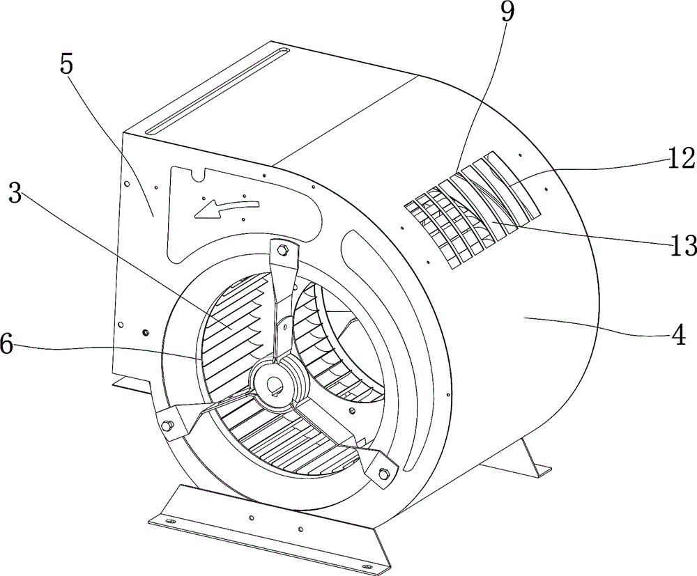
[0019] see Figure 1 to Figure 4 , the present invention provides a novel volute centrifugal fan with a permanent magnet brushless motor system, including a volute 1, an outer rotor motor 2 erected in the volute 1, and an impeller 3 outside the outer rotor motor 2, the impeller 3 is located in the volute 1, and the impeller 3 is connected with the outer rotor motor 2. The volute 1 is composed of a volute plate 4 and side plates 5 located on both sides of the volute plate. The side plates 5 on both sides are provided with air inlets 6. The volute 1 One side is provided with an air outlet 7, and an air duct is formed between the volute 1 and the impeller 3; the center position of the air outlet 7 is a horizontal plane 8, and the part of the worm plate 4 on the horizontal plane 8 is provided with an opening 9; The opening 9 is equipped with a...


PUM


Abstract

The invention provides a novel volute centrifugal fan provided with a permanent-magnet brushless motor system. The novel volute centrifugal fan provided with the permanent-magnet brushless motor system comprises a volute, an outer rotor motor mounted in the volute through a support, and an impeller arranged outside the outer rotor motor in a sleeving mode. The impeller is located in the volute and connected with the outer rotor motor. The volute is composed of a volute plate and side plates located on the two sides of the volute plate. Air inlets are formed in the side plates on the two sides. An air outlet is formed in one side of the volute. An air duct is formed between the volute and the impeller. With the center of the air outlet as the horizontal plane, an opening is formed in the portion, located on the horizontal plane, of the volute plate. A bridge arch type radiator matched with the opening is mounted at the opening. According to the novel volute centrifugal fan provided with the permanent-magnet brushless motor system, the heat dissipation effect of a driver can be changed according to the change of a load of the centrifugal fan, and the large the load is, the better the heat dissipation effect of the driver is, so that it is guaranteed that the driver is in a low-temperature operating state, the operating efficiency of the driver is improved, and the service life of the driver is prolonged.

Description

technical field [0001] The invention relates to a novel volute centrifugal fan with a permanent magnet brushless motor system. Background technique [0002] The traditional volute centrifugal fan includes the volute fan and the permanent magnet brushless motor system used for driving. The magnetic brushless motor system is separated, including the permanent magnet brushless motor body and the driver. The heat dissipation of the driver is basically through natural air, but this cooling method has low heat dissipation efficiency, especially when the centrifugal fan has a large air volume and pressure. The driver is under high temperature operation, directly affects the life and efficiency of the drive. [0003] And with the improvement of energy efficiency and the convenience of customers, the "easy installation, plug and play, high efficiency and energy saving" integral volute centrifugal fan with permanent magnet brushless motor system has become an urgent need in the venti...

Claims


Application Information

Patent Timeline
Patent Type & Authority Applications(China)
IPC IPC(8): F04D25/08F04D29/58F04D29/42F04D29/44
CPCF04D25/082F04D29/4226F04D29/441F04D29/5806H02K5/18F04D17/16F04D25/068F04D29/5813F04D29/283F04D29/424F04D25/08F04D29/582F04D29/4233F04D29/5826
Inventor 章启忠张唯
Owner ZHE JIANG YILIDA VENTILATOR CO LTD
Why Eureka
Try Eureka