Differential pressure type thermal coupling rectification device

A thermally coupled, differential pressure technology, applied in the field of rectification, can solve the problems of affecting production costs, large energy consumption in the rectification process, and large steam consumption, and achieve the effect of saving steam consumption, obvious energy saving effect and improving production efficiency.

Active Publication Date: 2017-01-18
NINGBO JUHUA CHEM TECH CO LTD +1
View PDF7 Cites 2 Cited by
  • Summary
  • Abstract
  • Description
  • Claims
  • Application Information

AI Technical Summary

Problems solved by technology

The vapor-liquid reflux forms a vapor-liquid two-phase in countercurrent contact, so that relatively pure single-component products are obtained at both ends of the tower, but the rectification process consumes a lot of energy. The earliest thermocouple rectification was proposed by Petlyuk 50 years ago Yes, research has found that thermocouple rectification saves at least 30% more energy than conventional rectification processes, but it is difficult to industrialize due to the technical conditions at that time. With the improvement of control technology, the research on thermocouple rectification tends to be active again, but in the production process, although the method of differential pressure coupled rectification is used for purification, one feed port is used, and the rectification tower mostly adopts a single fixed Tray type, high pressure difference, high energy consumption, unable to obtain high-purity rectified substances, and its own structure leads to large steam consumption, seriously affecting production costs, and can no longer meet the needs of current technological development

Method used


Image

  • Differential pressure type thermal coupling rectification device

Examples


Embodiment Construction

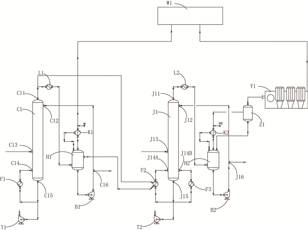
[0016] The present invention will be further described below in conjunction with the accompanying drawings and specific embodiments, taking tetrachlorethylene rectification as an example.

[0017] see figure 1Shown, a kind of differential pressure type thermally coupled rectification device comprises atmospheric tower equipment group and vacuum tower equipment group, it is characterized in that, described atmospheric tower equipment group comprises atmospheric tower tower body C1) and is connected by pipeline Each atmospheric equipment group, the inner wall of the atmospheric tower body C1 is provided with a plurality of scalable baffles, and the expansion and contraction of the baffles is controlled by a flow meter arranged in the atmospheric tower body, and the atmospheric tower body C1 is provided with a first material inlet C13, a first material outlet C16, a first liquid inlet C12, a first liquid outlet C15, a first air inlet C14, and a first gas outlet C11. The atmospher...


PUM


Abstract

The invention discloses a differential pressure type thermal coupling rectification device. The device comprises an atmospheric tower equipment group and a vacuum tower equipment group, wherein the atmospheric tower equipment group comprises an atmospheric tower body and all atmospheric equipment which is connected with one another through pipelines; a plurality of extensible baffles are arranged on the inner wall of the atmospheric tower body; the expansion of the baffles is controlled through a flow meter arranged in the atmospheric tower body; the vacuum tower equipment group comprises a vacuum tower body and all vacuum equipment groups connected with the vacuum tower body; a liquid distributor is arranged on the inner wall of the vacuum tower body. The device adopting the structure can obtain high-purity products, cancels steam in the conventional sense, applies energy at the top of a prior tower to the evaporation of a second tower, can save the steam amount for a rectifying tower, and realizes energy saving, moreover, as an atmospheric tower and a vacuum tower are respectively provided with two sets of pipelines, when any one of the atmospheric tower or the vacuum tower breaks down, standby pipelines can be started, shutting down due to equipment failure cannot occur, and the production efficiency is effectively improved.

Description

technical field [0001] The invention relates to the technical field of rectification, in particular to a differential pressure thermal coupling rectification device. Background technique [0002] Rectification is a distillation method that uses reflux to obtain high-purity separation of liquid mixtures. The key to the complete separation of liquid mixtures in rectification lies in the application of reflux. The reflux includes both a liquid with a high concentration of volatile components at the top of the column and a vapor with a high concentration of less volatile components at the bottom of the column to return to the column. The vapor-liquid reflux forms a vapor-liquid two-phase in countercurrent contact, so that relatively pure single-component products are obtained at both ends of the tower, but the rectification process consumes a lot of energy. The earliest thermocouple rectification was proposed by Petlyuk 50 years ago Yes, research has found that thermocouple rec...

Claims


Application Information

Patent Timeline
Patent Type & Authority Applications(China)
IPC IPC(8): B01D3/14B01D3/42C07C17/383C07C21/12
CPCB01D3/143B01D3/42C07C17/383C07C21/12
Inventor 周强黄波钟骏良吴刚应仲阳侯义贵徐国飞宋李雁
Owner NINGBO JUHUA CHEM TECH CO LTD
Why Eureka
Try Eureka