A microgrid system and a control method for the microgrid system

A micro-grid and micro-power technology, applied in the direction of power network operating system integration, information technology support systems, electrical components, etc., can solve the problems of insufficient load power supply, reduce the safety and reliability of the micro-grid system, energy utilization, and division, etc. Achieve smooth and seamless switching, improve safety, reliability and energy efficiency

Active Publication Date: 2019-01-08
XINZHI ENERGY SYST CONTROL
View PDF4 Cites 0 Cited by
  • Summary
  • Abstract
  • Description
  • Claims
  • Application Information

AI Technical Summary

Problems solved by technology

[0003] However, the existing micro-grid system generally has the following problems: when a sudden failure occurs in the external power grid, the existing micro-grid system cannot immediately divide a suitable island according to the power that the micro-power supply unit can supply and the power required by the load unit range, and before the appropriate island range is divided, the micro power supply in the micro power supply unit is not enough to supply power to all the loads in the load unit, so that before the appropriate island range is divided, all the loads in the micro grid system In the state of power outage, that is to say, when the external power grid suddenly fails, the existing microgrid system cannot guarantee smooth and seamless switching from the grid-connected state to the off-grid state
In addition, the existing micro-grid system can only divide the island range once, and cannot guarantee the balance between the power supplied by the micro-power unit and the power required by the load unit, thus reducing the safety and reliability of the micro-grid system. and energy efficiency

Method used


Image

  • A microgrid system and a control method for the microgrid system
  • A microgrid system and a control method for the microgrid system
  • A microgrid system and a control method for the microgrid system

Examples


Embodiment 1

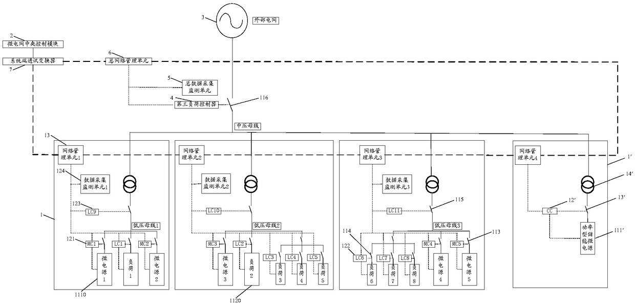
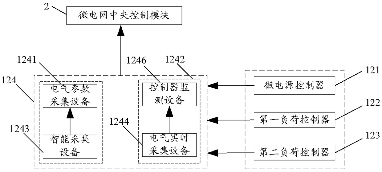
[0049] Such as figure 1 As shown, this embodiment provides a microgrid system, the microgrid system includes at least one first block 1, at least one second block 1', and each first block 1 and each second block 1 'The central control module 2 of the connected microgrid, the first block 1 includes the connected microgrid energy supply module 11 and the terminal data acquisition and control module 12, and the second block 1' includes the medium voltage energy storage module 11'.

[0050] When the microgrid system is in the grid-connected state, the medium-voltage energy storage module 11' is connected to the external grid 3, and when the micro-grid system is in the off-grid state, the medium-voltage energy storage module 11' is disconnected from the external grid 3. The medium-voltage energy storage module 11' is used to provide power for all loads 1120 in the micro-grid system before the micro-grid system enters an island operation mode in an off-grid state.

[0051] When the...

Embodiment 2

[0090] This embodiment provides a control method for a microgrid system, which is applied to the microgrid system described in Embodiment 1, such as Figure 9 As shown, the microgrid control method specifically includes:

[0091] Step S1: Predict the maximum discharge power P of the medium voltage energy storage module in real time MAX , the power that can be supplied by each micro power supply in the micro power supply unit, and the power required by each load in the load unit;

[0092] Step S2: Calculate the total power P required by the full load of the microgrid system in real time L ;

[0093] Step S3: Determine in real time whether the microgrid system needs to be disconnected from the external grid, and if so, determine the predicted maximum discharge power P of the medium-voltage energy storage module at the current time point MAX Is it greater than or equal to the calculated total power P required by all loads in the microgrid system L , if yes, then enter step S4...


PUM


Abstract

The invention provides a micro-grid system and a control method thereof, and relates to the technical field of micro grids. The micro-grid system can smoothly switch to an off-grid state from a grid-connected state. The micro-grid system comprises a first block, a second block and a micro-grid central control module, a medium-voltage energy storage module of the second block provides power for all loads in the system before the system enters isolated island operation from the off-grid state, a micro power supply in a micro-grid energy using module of the first block supplies power for a load unit after the system enters isolated island operation from the off-grid state, the micro-grid central control module predicts maximum discharge power of the medium-voltage energy storage module, power supplied by a micro power supply unit and power needed by the load unit and issues instructions after the system is in the off-grid state, and a terminal data acquisition and control module of the first block invests or removes the loads under control of the instructions. The micro-grid system is used for independently supplying power for the loads in the off-grid state.

Description

technical field [0001] The invention relates to the technical field of distributed energy generation and micro-grid control, in particular to a micro-grid system and a control method for the micro-grid system. Background technique [0002] Microgrid system is an intelligent and controllable small grid system that combines distributed power generation system, energy storage and terminal load, and it is an autonomous system that can realize self-control, protection and management. The microgrid system mainly includes a micro power supply unit for supplying power and a load unit for consuming power. Wherein, the micro power supply unit includes at least one micro power supply, and the load unit includes at least one load. Compared with the external grid, the microgrid system has two operating modes: grid-connected and off-grid: when the external grid supplies power normally, the micro power supply in the microgrid system is incorporated as an auxiliary power supply, and transm...

Claims


Application Information

Patent Timeline
Patent Type & Authority Patents(China)
IPC IPC(8): H02J3/00H02J3/14
CPCH02J3/005H02J3/14H02J3/388Y02B70/3225Y04S20/222
Inventor 李华印石大鹏李新新王玉亮尧军陈灿章贺万普
Owner XINZHI ENERGY SYST CONTROL
Why Eureka
Try Eureka