A sealing structure for sealing valve
A sealing structure and sealing valve technology, applied in the field of ball valve sealing, can solve the problems of sealing surface leakage, medium sealing side and outer ring leakage, etc., and achieve the effect of strengthening sealing ability, improving sealing effect and firm fixing
- Summary
- Abstract
- Description
- Claims
- Application Information
AI Technical Summary
Problems solved by technology
Method used
Image
Examples
Embodiment 1
[0053] Independent claim 1 describes a sealing structure for sealing valves,
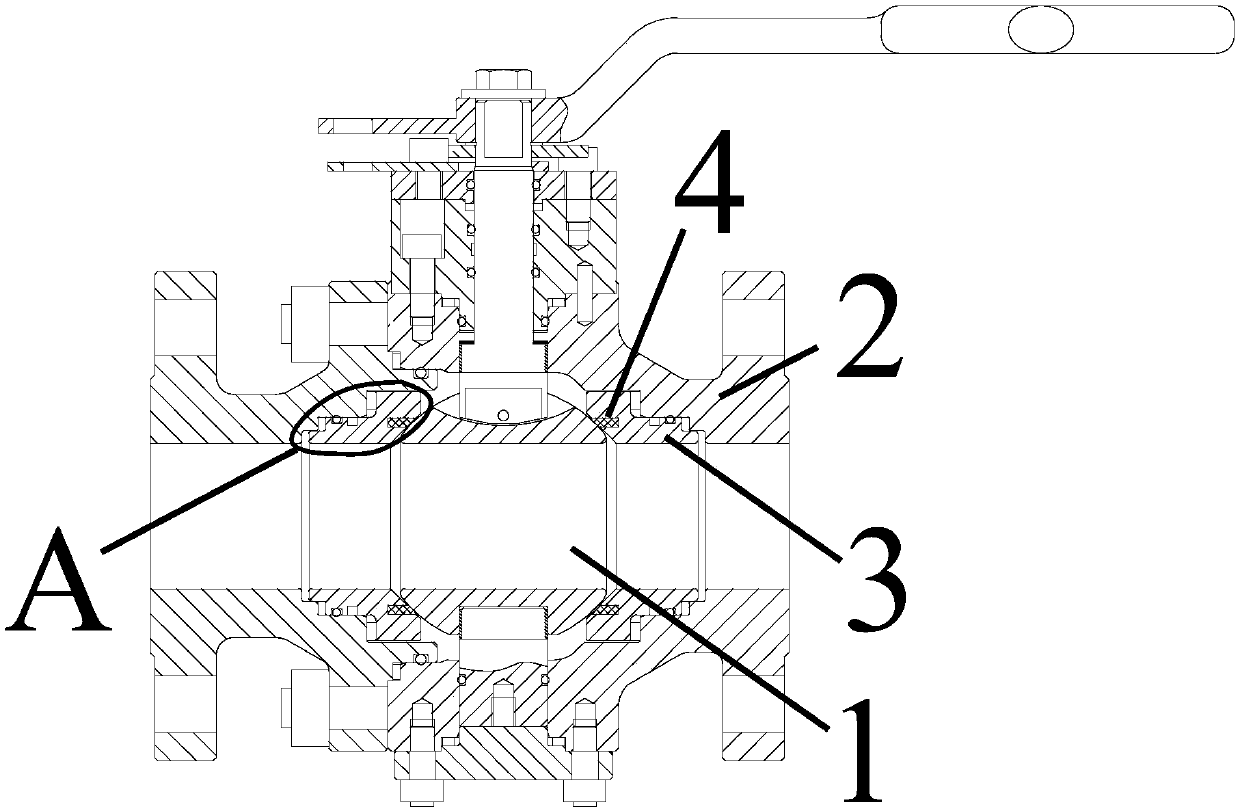
[0054] Such as figure 1 As shown, the sealing valve includes: a valve core 1, a valve body 2, and a retainer 3 arranged between the valve core 1 and the valve body 2, the above-mentioned valve core 1 is a spherical valve core; the sealing structure includes:
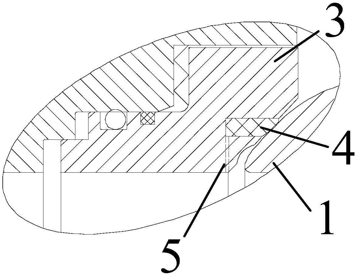
[0055] Such as figure 2 As shown, the sealing ring 4 is set in the vertical direction between the retainer 3 and the valve core 1, and is snapped into the annular groove of the inner cavity of the retainer 3; the sealing ring 4 faces the valve spool 1 is biased and sealingly engaged with said spool 1;
[0056] The sealing ring 4 is in interference fit with the annular groove, and an exhaust groove is provided between the inner ring and the annular groove for discharging the air in the annular groove during the installation of the sealing ring 4 .
[0057] The above-mentioned sealing ring is arranged in the annular groove of the inner cavi...
Embodiment 2
[0077] Such as figure 1 As shown, the sealing valve includes: a valve core 1, a valve body 2, and a retainer 3 arranged between the valve core 1 and the valve body 2, the above-mentioned valve core 1 is a spherical valve core; the sealing structure includes:
[0078] Such as figure 2 As shown, the sealing ring 4 is set in the vertical direction between the retainer 3 and the valve core 1, and is snapped into the annular groove of the inner cavity of the retainer 3; the sealing ring 4 faces the valve spool 1 is biased and sealingly engaged with said spool 1;
[0079] The sealing ring 4 is in interference fit with the annular groove, and an exhaust groove is provided between the inner ring and the annular groove for discharging the air in the annular groove during the installation of the sealing ring 4 .
[0080] The above-mentioned sealing ring is arranged in the annular groove of the inner cavity of the retainer, and is biased and sealed toward the spherical valve core, so...
Embodiment 3
[0100] Such as figure 1 As shown, the sealing valve includes: a valve core 1, a valve body 2, and a retainer 3 arranged between the valve core 1 and the valve body 2, the above-mentioned valve core 1 is a spherical valve core; the sealing structure includes:
[0101] Such as figure 2 As shown, the sealing ring 4 is set in the vertical direction between the retainer 3 and the valve core 1, and is snapped into the annular groove of the inner cavity of the retainer 3; the sealing ring 4 faces the valve spool 1 is biased and sealingly engaged with said spool 1;
[0102] The sealing ring 4 is in interference fit with the annular groove, and an exhaust groove is provided between the inner ring and the annular groove for discharging the air in the annular groove during the installation of the sealing ring 4 .
[0103] The above-mentioned sealing ring is arranged in the annular groove of the inner cavity of the retainer, and is biased and sealed toward the spherical valve core, so...
PUM
 Abstract
Description
Claims
Application Information
 - R&D
- Intellectual Property
- Life Sciences
- Materials
- Tech Scout
- Unparalleled Data Quality
- Higher Quality Content
- 60% Fewer Hallucinations
Browse by: Latest US Patents, China's latest patents, Technical Efficacy Thesaurus, Application Domain, Technology Topic, Popular Technical Reports.
© 2025 PatSnap. All rights reserved.Legal|Privacy policy|Modern Slavery Act Transparency Statement|Sitemap|About US| Contact US: help@patsnap.com


