
Cutting device for nano-glass production

A cutting equipment and nano-glass technology, applied in glass manufacturing equipment, glass cutting devices, manufacturing tools, etc., can solve the problems of uneven cutting, high energy consumption, cumbersome operation, etc., so as not to be easily broken and prolong the service life , The effect of not easy to rust

Pending Publication Date: 2017-01-11
麻城小龟龟机械科技有限公司
View PDF5 Cites 27 Cited by
  • Summary
  • Abstract
  • Description
  • Claims
  • Application Information

AI Technical Summary

Problems solved by technology

[0006] In order to overcome the disadvantages of cumbersome operation, high energy consumption and uneven cutting in the current nano glass cutting device, the technical problem to be solved by the present invention is to provide a cutting device for nano glass production with convenient operation, low energy consumption and uniform cutting. equipment

Method used


Image

  • Cutting device for nano-glass production
  • Cutting device for nano-glass production
  • Cutting device for nano-glass production

Examples


Embodiment 1

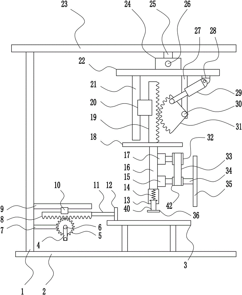
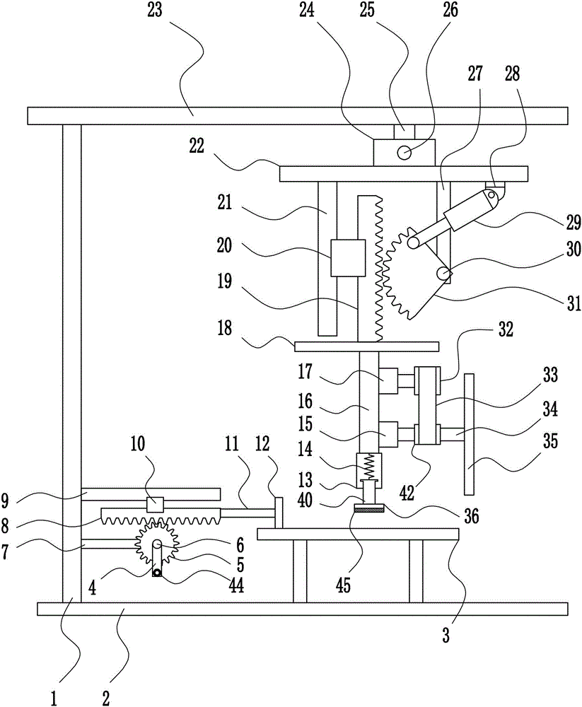
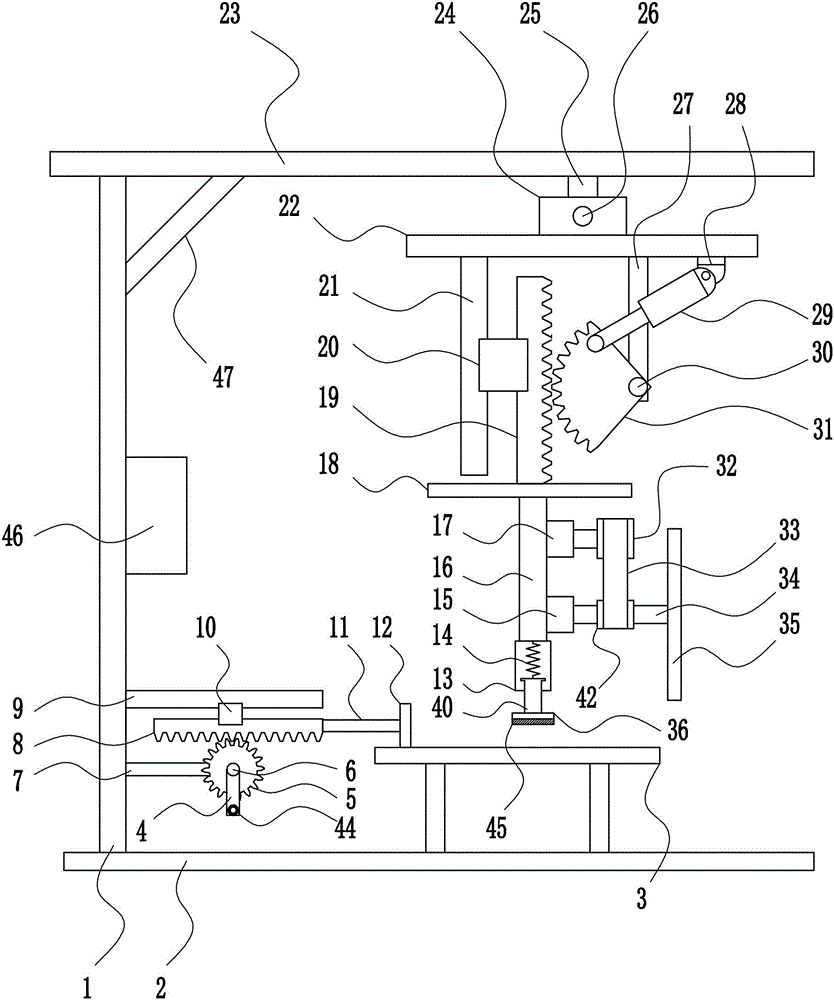
[0037] A cutting device for nano glass production, such as Figure 1-6 As shown, it includes a left frame 1, a bottom plate 2, a placement table 3, a crank handle 4, a circular gear 5, a first rotating shaft 6, a first bearing seat 7, a first rack 8, a first slide rail 9, a first Slider 10, push rod 11, push block 12, sleeve 13, elastic member 14, second bearing seat 15, first fixed plate 16, first motor 17, second fixed plate 18, second rack 19, the first Second slider 20, second slide rail 21, third fixed plate 22, top plate 23, guide sleeve 24, nut 25, guide post 26, fixed rod 27, swing seat 28, electric push rod 29, hinged part 30, sector gear 31. Large pulley 32, flat belt 33, second rotating shaft 34, blade 35, briquetting block 36, second motor 37, third bearing seat 38, screw mandrel 39, moving rod 40, fourth bearing seat 41 and small pulley 42 , the left frame 1 is welded on the left side of the top of the bottom plate 2, the placing table 3 is connected to the right...


PUM


Abstract

The invention relates to a cutting device, in particular to a cutting device for nano-glass production, wherein the cutting device is convenient to operate, low in energy consumption and uniform in cutting. The cutting device for nano-glass production comprises a left frame, a bottom plate, a placement table, a rocking handle, a circular gear, a first rotating shaft, a first bearing block, a first rack, a first sliding rail, a first slider, an ejector rod and the like, the left side of the top of the bottom plate is welded with the left frame, the right side of the top of the bottom plate is connected with the placement table in a bolted manner, the lower portion of the right side of the left frame is connected with the first bearing block and the first sliding rail in a bolted manner. An electric push rod drives a sector gear to swing, the sector gear drives a second rack to move downwards, and vertical movement of a blade is realized through matching of a second motor with a lead screw and a nut.

Description

technical field [0001] The invention relates to a cutting device, in particular to a cutting device for nano glass production. Background technique [0002] Nanoglass refers to a special glass material whose internal organization is structurally controlled, forming a special glass material with a size ranging from about 1nm to hundreds of nanometers. This kind of structure control can be to control the structure of the glass blank (base material) at the atomic or molecular level, it can be to form ultrafine particles inside the glass, or it can be dispersed to form another substance (heterogeneous phase). Through this structure control, the nano glass can maintain its glass properties, and at the same time endow it with many new properties such as mechanical properties and optical properties that are different from ordinary glass. Nanoglass is mainly used in heat insulation and UV protection of glass curtain walls, high-end hotels, hotels, office buildings, private houses, ...

Claims


Application Information

Patent Timeline
IPC IPC(8): C03B33/00
CPCC03B33/00
Inventor 肖毅
Owner 麻城小龟龟机械科技有限公司
Learn More