
Automatic winding device for cable

A technology of automatic winding and driving device, which is used in transportation and packaging, transportation of filamentous materials, thin material processing, etc. It can solve the problems of uneven arrangement, low winding efficiency, waste of manpower, etc. , The effect of simple structure and convenient operation

Inactive Publication Date: 2017-01-11
YUNCHENG POWER SUPPLY COMPANY OF STATE GRID SHANXI ELECTRIC POWER +1
View PDF8 Cites 22 Cited by
  • Summary
  • Abstract
  • Description
  • Claims
  • Application Information

AI Technical Summary

Problems solved by technology

[0002] Winding the cable on the cable reel is the most common way to store the cable, while the traditional winding method is to manually wind the cable, the winding speed is slow and the efficiency is low, and for large cables, the weight is heavy and manual winding The wire wastes a lot of manpower, and the labor intensity is high. In the prior art, there are some methods of winding the cable through the motor-driven reel, but the structure is usually complicated and inconvenient to use. The uneven arrangement on the core barrel of the cable reel causes the cables on the core barrel of the reel to overlap to form protrusions and depressions, so that the cable reel cannot continue to be wound normally, resulting in low winding efficiency, which is of great concern to the electric workers. Inconvenience at work

Method used


Image

  • Automatic winding device for cable
  • Automatic winding device for cable
  • Automatic winding device for cable

Examples


Embodiment Construction

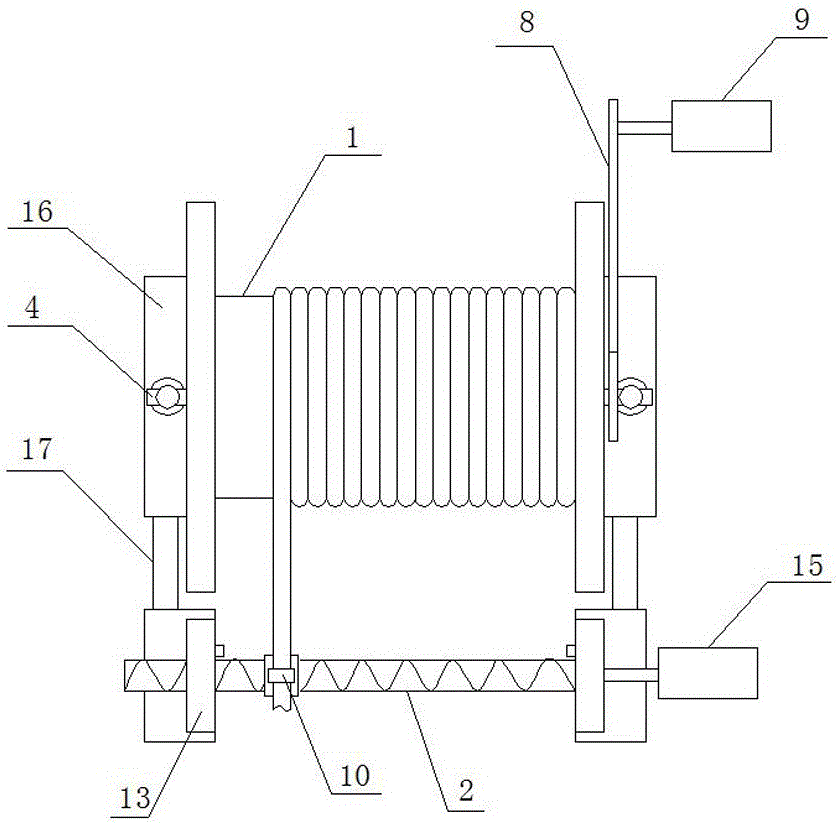
[0021] Such as Figure 1~Figure 4 As shown, the automatic cable winding device of the present invention includes a wire winder 1 and a wire arranging device 2, and the wire winder 1 includes a winding barrel 3 and a support frame 4, and the support frame 4 is two, symmetrically arranged on The two ends of the bobbin 3, the support frame 4 includes a support leg 5 and a connecting shaft 6, the connecting shaft 6 is arranged horizontally, and one end of the connecting shaft 6 is arranged on the top end of the supporting leg 5 through a bearing, the The other end of the connecting shaft 6 is located at the center line of the bobbin 3, and the bobbin 3 rotates between the two supporting legs 5 through two connecting shafts 6, one of which is provided with a drive wheel 7. The transmission wheel 7 is connected with the winding device driving device 9 through the transmission chain 8;

[0022] The cable arrangement 2 includes a cable rack 10, a transmission screw 11, a guide rod 12...


PUM


Abstract

The invention discloses an automatic winding device for a cable and belongs to the field of cable storage. Winding displacement is performed on a rotating winding reel by the aid of a traverse, manual winding is omitted, uniform wiring can be realized, and the device is simple in structure and convenient to operate. According to the technical scheme, the device comprises a winding device and the traverse; the winding device comprises the winding reel and supporting frames; each supporting frame comprises a supporting leg and a connecting shaft; the winding reel rotates between the supporting legs by the aid of the connecting shafts; the traverse comprises a winding displacement frame, a transmission screw, a guide rod and supporting seats; the guide rod is arranged below the transmission screw in parallel; the middle of the winding displacement frame is matched with the transmission screw; the lower end of the winding displacement frame penetrates through the guide rod; a wire penetrating hole is formed above the winding displacement frame; the winding displacement frame moves along the guide rod through rotation of the transmission screw; reversing switches are arranged on the supporting seats; and the transmission screw is rotated by the aid of a traverse driving device.

Description

technical field [0001] The invention relates to an automatic cable winding device, which belongs to the technical field of cable storage. Background technique [0002] Winding the cable on the cable reel is the most common way to store the cable, while the traditional winding method is to manually wind the cable, the winding speed is slow and the efficiency is low, and for large cables, the weight is heavy and manual winding The wire wastes a lot of manpower, and the labor intensity is high. In the prior art, there are some methods of winding the cable through the motor-driven reel, but the structure is usually complicated and inconvenient to use. The uneven arrangement on the core barrel of the cable reel causes the cables on the core barrel of the reel to overlap to form protrusions and depressions, so that the cable reel cannot continue to be wound normally, resulting in low winding efficiency, which is of great concern to the electric workers. Inconvenience at work. C...

Claims


Application Information

Patent Timeline
Patent Type & Authority Applications(China)
IPC IPC(8): B65H54/28
CPCB65H54/2866B65H2701/34
Inventor 贠鹏王勇杜平吉裴云芳郑多佳
Owner YUNCHENG POWER SUPPLY COMPANY OF STATE GRID SHANXI ELECTRIC POWER
Learn More