Unpowered aircraft

An aircraft and power technology, applied in the field of non-powered flying tools and permanent non-powered fixed hovering in the air, can solve the problems of high manufacturing and use costs, achieve the effects of low production cost, simple process, and improved structural strength

Inactive Publication Date: 2017-01-11
成立
View PDF5 Cites 0 Cited by
  • Summary
  • Abstract
  • Description
  • Claims
  • Application Information

AI Technical Summary

Problems solved by technology

Very expensive to make, use, manage, etc. because of the power required

Method used


Image

  • Unpowered aircraft
  • Unpowered aircraft

Examples


Embodiment 1

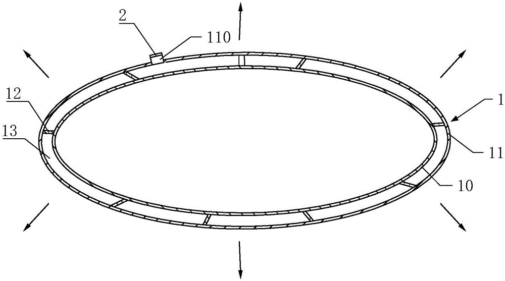
[0021] like figure 1 As shown, an unpowered aircraft includes a body 1 made of soft elastic material. The body 1 includes an inner layer 10 and an outer layer 11 arranged inside and outside, a gap 13 is provided between the inner layer 10 and the outer layer 11, and a connecting portion 12 connecting the inner layer 10 and the outer layer 11 is provided in the gap 13, and the inner layer 10 It is a hollow structure. The main body 1 is provided with an inflation hole 110 , the inflation hole 110 communicates with the gap 13 between the inner layer 10 and the outer layer 11 , and the inflation hole 110 is provided with an inflation two-way valve 2 . After the inflatable two-way valve 2 is opened, air is inflated into the gap 13 through the inflation hole 110, and the air in the gap makes the outer layer expand outwards. When it expands, the connecting part pulls the inner layer to expand together, changing the relative volume of the inner layer 10. The air is expelled, and the...

Embodiment 2

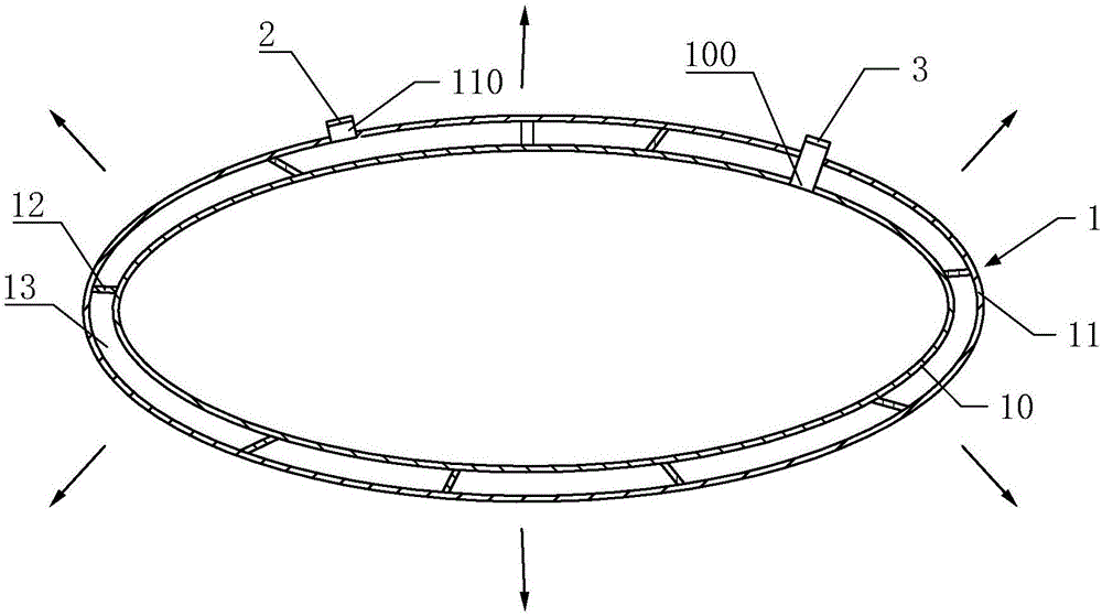
[0031] like figure 2 As shown, this embodiment is basically the same as Embodiment 1, the difference is:

[0032] The main body 1 may also be provided with an air extraction hole 100 , the air extraction hole 100 communicates with the inner layer 10 , and an air extraction two-way valve 3 is provided on the air extraction hole 100 .

[0033] When the unpowered aircraft of this embodiment is put into use, the inner layer 10 can be in an inflated state, and the inside can be filled with air. When adjusting the operation of the suction two-way valve 3, the air in the inner layer 10 is discharged out of the body 1 through the air suction hole 100, and the volume of the inner layer 10 is reduced; at the same time, the inflation two-way valve 2 is adjusted so that the air enters the gap 13 through the inflation hole 110, When inflation is realized, the gas filled in the gap 13 generates pressure, which makes the body 1 expand as a whole, and the expansion process makes the outer l...


PUM


Abstract

The invention discloses an unpowered aircraft. The unpowered aircraft comprises a body; the body is made of a soft elastic material so that the body can generate non-rigid elastic deformation. The body is divided into an inner layer and an outer layer; a gap is reserved between the inner layer and the outer layer; a connecting part which is simultaneously connected with the inner layer and the outer layer is arranged in the gap. An inflating hole is also formed in the body; the inflating hole is communicated with the gap; an inflating two-way valve is arranged on the inflating hole. When the inflating two-way valve inflates air into the gap through the inflating hole, the outer layer pulls the inner layer to expand together, finally the volume of the body becomes larger, and equivalently, part of atmosphere is exhausted from the body to generate lifting buoyancy force f, so that unpowered flight of the unpowered aircraft is realized. Therefore, the unpowered aircraft disclosed by the invention has the advantages of low manufacturing cost and simple process, can be applied to a transportation navigating tool to complete air transportation instead of flight, and can also be applied to implementing the flight of an automobile; the unpowered aircraft has the characteristics of permanent lifting, and can be used for lifting a castle in air to realize air living and even realize a marine lifting living environment.

Description

technical field [0001] The invention relates to the technical field of non-powered flying tools and permanent non-powered fixed hovering in the air, in particular to a non-powered aircraft. Background technique [0002] There have been two modes in the history of unpowered lifting. One is the hot air balloon mode. Its principle is to heat the air in a non-enclosed balloon, reduce the air density, increase the lifting force, and achieve buoyancy. This is somewhat similar to the Chinese Kongming Lantern. But the hot-air balloon of this structure has the shortcoming that application is difficult to master. The other is to change the gas lighter than air in the closed balloon, such as hydrogen or helium and other gases with lower density than air, and use the density difference to make the closed balloon float up. However, the air filled in this kind of closed balloon is either easy to explode, or the lifting effect is poor, and other technical reasons are finally eliminated by...

Claims


Application Information

Patent Timeline
IPC IPC(8): B64B1/02B64B1/62
CPCB64B1/02B64B1/62
Inventor 成立
Owner 成立
Why Eureka
Try Eureka